Everything About MojoWorld
Info, Documentation, Downloads
R.I.P. Ken Musgrave (1955 - 2018)
MojoWorld -- developed by Ken Musgrave -- was a program focused on generating planets and sprawling landscapes through fractals and advanced mathematics. Its most widely known use case was when Jason Kapalka developed a fascination with its capabilities of rendering otherworldly artificial planetary landscapes and encouraged its usage for the Bejeweled 2 backdrops which were licensed (and possibly later commissioned?) from Armands Auseklis. However, it also found its way into movie/film production. Apparently NASA took interest in the program and provided additional funding so that it could be updated to properly handle satellite surface data from Mars. Similar but not quite identical competing products were: Vue, Terragen, and Bryce.
Someone recently asked me some questions about MojoWorld, I couldn't answer them due to the absolute lack of any remaining information about the program (search engines are dead and LLMs are as useful as a wet stinking sock for research)... I've decided to archive everything I could find and learned, as well as the useful Pandromeda help documents, along with reclaimed freeware binaries. I have been sitting on my hands with MojoWorld for the past 20 years... better late than never?
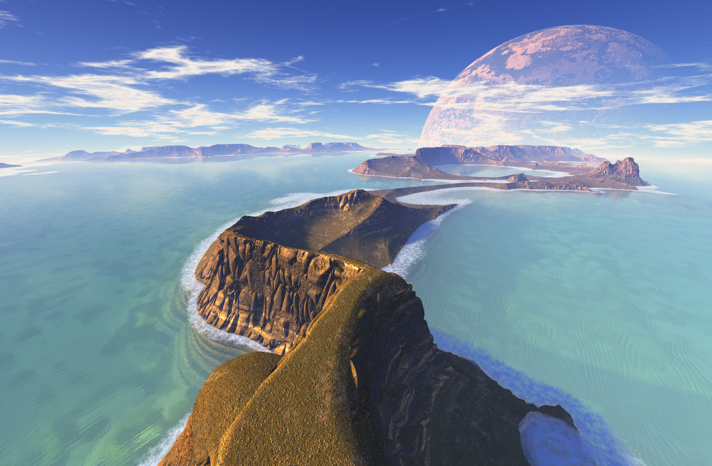
One of Ken Musgrave's awesome MojoWorld renders of the "Dale Peninsula" planet, Armands Auseklis also has an alternative take on it along with some post-production edits.
Index: Product Info, Downloads, The MojoWorld Archives, Videos, Tutorials (Archived from Pandromeda), MojoWorld Feature Tour (Archived from Pandromeda), Bejeweled 2 & Twist MojoWorld Backgrounds
Product Info
Create and explore your own worlds, your way.
Look up, look down, look all around you—only MojoWorld 3 puts you on a complete planet with perfect detail everywhere you go. It's just like being there! There's never been anything like this before: MojoWorld is literally a window on a parallel universe full of planets as real as planet Earth.
The revolutionary MojoWorld 3 product line turns you loose in these incredible worlds to create, sculpt, and populate them to realize your personal vision, in infinite detail. MojoWorld's amazing procedural fractal engine creates pixel-level detail at any resolution, distance, or field of view, for realism the likes of which you've never seen before—except in reality!
3D artists, graphic designers, game developers, animators, and video professionals alike will discover the perfect combination of ease of use and power for all your terrain- and world-building needs.
It was ultimately released in three commercial flavours: MojoWorld Focus, MojoWorld Standard, and MojoWorld Professional. MojoWorld Viewer was a free release that allowed viewing and rendering MojoWorld projects to a maximum size of 1024x465 ("Wow!") along with an added watermark. MojoWorld Transporter was an earlier product free product that allowed basic parameter changes and exploration of files.
Versions by year of release
| Version | Year of Release |
|---|---|
| MojoWorld 1.0 | 2001 |
| MojoWorld 2.0 | 2002 |
| MojoWorld 3.0 | 2004 |
| MojoWorld 3.1 | 2005 |
| MojoWorld 3.1.1 | 2005 |
Recommended System Requirements
| Windows | Macintosh |
|---|---|
| Windows 98SE, 2000 or XP Pentium 3 / Althon Processor - 1GHz or higher 32MB 3D Graphics Card Open GL™ Quicktime 5.0 or later 256MB available RAM 350MB hard disk space (typical install) |
MacOS 9 or X Power PC G4 processor or higher 32MB 3D Graphics Card Open GL™ Quicktime 5.0 or later 256MB available RAM 350MB hard disk space (typical install) |
Feature Comparison
| Feature | MojoWorld Focus | MojoWorld Standard | MojoWorld Professional |
|---|---|---|---|
| Ability for Extra Modules | N | Y | Y |
| Horizon Clouds | N | N | Y |
| Crater Nodes | N | N | Y |
| Boulders | N | Y | Y |
| Importing Bryce into MojoWorld | N | Y | Y |
| Exporting Global Maps | N | Y | Y |
| Distributed Rendering | N | Y | Y |
| PlanetWizard | Y | Y | Y |
| MojoGraph Pro UI | N | N | Y |
| MojoMove | N | N | Y |
| MojoTree | N | N | N |
| MojoFrames | N | N | N |
Note: I built this chart to the best of my preliminary knowledge, there may be errors and omissions. Pandromeda shockingly never created an actual feature comparison chart, at least not one I could find.
Downloads
Pandromeda Freeware
Note: the viewer still needed a registration code despite being freeware: it was once generated by the now defunct account registration from Pandromeda. Still, I'll leave the binaries up for archival purposes. I was not able to find the freeware installers for MojoWorld Transporter 1.1.0 nor MojoWorld Transporter 1.2. While MojoWorld Transporter did have a Linux release (I assume one of their scientific clients requested it), Transporter's functionality was very limited and didn't render scenes which is what I imagine most people care about for the product.
Krummen Hacker's (and XenoArch's) plugins for MojoWorld 3.0
| Plugin Name | Notes | Plugin for Windows | Plugin for Mac | Sample World | Sample Render |
|---|---|---|---|---|---|
| KH_ZFractals | KH_ZFractals.zip | KH_ZFractals.dll.sit | JuliaDiving.mov (4MB) |
||
| KH_Quantum | KH_Quantum.zip | KH_Quantum.dll.sit | Challenge 30 | ||
| KH_BreakingWaves | KH_BreakingWaves.zip | KH_BreakingWaves.dll.sit | Wavy Planet | ||
| KH_WaterDepth | KH_WaterDepth.zip | KH_WaterDepth.dll.sit | Wavy Rivers | ||
| KH_Atmos | KH_Primitives now have mountains and oceans. Behaves almost like a planet! |
KH_Atmos.zip | KH_Atmos.dll.sit | TorusWorld QTVR (450KB) |
|
| KH_Mover | KH_Mover.zip | KH_Mover.dll.sit | |||
| KH_Nurbs | Point editing has totally changed. Use ALT to add or delete points Use SHIFT to move points at constant height. |
KH_Nurbs.zip | KH_Nurbs.dll.sit | ||
| KH_Avion | KH_Avion.zip | KH_Avion.dll.sit | Flying Cessna | FlyingCessna.mov (300KB) |
|
| All the above plugins | Stored in a single archive file. | KH_Plugins.zip | MacKHplugins.sit | ||
| XA_Function | Special thanks to XenoArch who gave me the source code as a gift to the MojoWorld community. | XA_Function.zip | XA_Function.dll.sit |
It does not appear any of these files have survived capture or in KhMojoWiki. I resuscitated as many as I could from dark corners of the internet. Anyone is free to provide the missing ones to me and I will gladly update the table. With that said... if you want all of these plugins (KH + XA) for a fresh Windows 3.1.1 install, as well as the special "3.0 dlfunctions" and volumetrics, download this complete package and drop it in (~ \MojoWorld3\plugins):
Dmytry Lavrov's MojoWorld Plugins/Downloads
Lewis Moorcroft's MojoWorld Downloads
The MojoWorld Archives
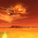
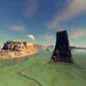
Here is a mirror of the planet files that were present on mojoworld.info, or more specifically mojoworld.3dvitality.com:
- Planets - All From 2002
- Planets - All From 2003
- Planets - All From 2004
- Planets - All From 2005
- Planets - All From 2006
- Planets - All From 2007
3DC Challenge Planets
All available planets from the 3D commune challenges from the year 2002 to 2007. Special thanks to woz2002 for submitting the collection.
Challenge? Which Challenge?
There was a 3D web community, 3dcommune.com . Sadly the portal doesn't longer exist due some unfortunately circumstances. At 3dcommune met the most of the MojoWorld users and discussed the software they loved and their works.
Soon the idea of a regulary challenge was born. One or more artists provided the "Planet of the Week". Each participant was then called to upload up to 3 images from the "travels" on this planet. Then a winner has been found by voting.
This tradition continued until 2007. Unfortunately, then slowly crumbled the community, which was also for one reason the fact that MojoWorld was no longer being developed. Then 3DC was closed and most (hard-core) users switched to Renderosity.com.
The challenge was a very good reason to develop several skills on building fractal landscapes and to become better each time.
Videos
tikirussy's MojoWorld Videos:
ecmalo's MojoWorld Videos:
Mike Hill's MojoWorld Videos:
Mojoslav's MojoWorld Videos:
Lewis Moorcroft Art's MojoWorld Videos:
- Dawn Of The Winter Sun : Mojoworld Digital Art - Alien Planet
- Silence Is Golden : Mojoworld Digital Art - Alien Planet
- Silver Dawn : Mojoworld Digital Art - Alien Planet
- The Fallen : Mojoworld Digital Art - Alien Planet
- Dead To The World : Mojoworld Digital Art - Alien Planet
- Coming Home To The Sun : Mojoworld Digital Art - Alien Planet
- The Sun Rising : Mojoworld Digital Art - Alien Planet
Renderosity's MojoWorld Videos:
- Renderosity Gallery of the Week - MojoWorld
- Renderosity Gallery of the Week for Feb 4, 2019 - Mojoworld Gallery
- Gallery of the Week for August 2, 2021 - The MojoWorld Gallery
- Renderosity Gallery of the Week for Aug 28, 2017 - MojoWorld Gallery
- Renderosity Gallery of the Week for Sept 5, 2016 is the MojoWorld Gallery
- Renderosity Gallery of the Week for Nov 25, 2019 - Landscape Gallery
Garth Linden's MojoWorld Videos:
Cplouj's MojoWorld Videos:
Timmy Skwarchov's MojoWorld Videos:
Tutorials (Archived from Pandromeda)
All text and images remain property of Pandromeda Inc, they have only been reproduced here for historical, non-commercial, and preservation purposes. Archived source obtained from: http://www.mojoworld.org/tutorials/
Index: World Maps, MojoWorld Boulders, Crater Your MojoWorlds, Distributed Rendering, Bryce Into Mojo , Horizon Clouds
World Maps
Use the 'Export Planet' feature and your favorite image editing program to create global maps of your MojoWorlds. (Std / Pro)
You can create a world map of any planet, complete with longitude and latitude lines, with MojoWorld 3.
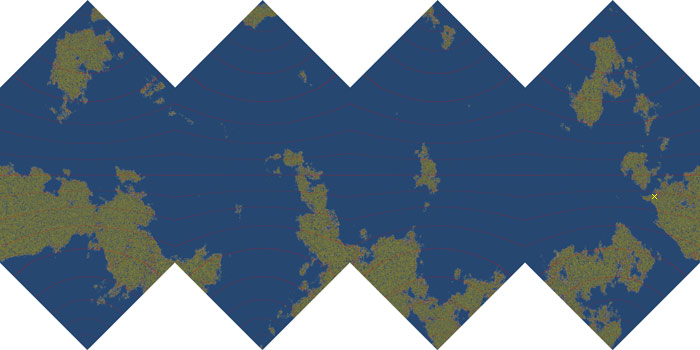
First, download my library item. This is a nested material tree which will allow you to select the color for your latitude lines and then plug in your existing global material underneath those lines. It also colors the sea bed blue, as when the export process happens, the ocean is not rendered. You can, of course, change the color of the sea bed by modifying the 'sea bed gradient' texture's gradient.
Open the world you want to map. Click the circle-M for the material on the planet. Make sure that the material applied to your planet has a name that you can easily identify.
Use the 'Load From Library' option to load the WorldMapLines.mjl The second leaf is for the color of the latitude lines. They're red by default, but that may not be suitable for all planets. (You could make your latitude lines out of some wacky color texture, but a solid color is probably best.)
The first leaf is a nested material tree. Open the leaf, then click the arrow to the left of the 'land / sea leaf' to open up the material editor. That material also has two leaves, the first of which is the 'sea bed gradient' and the second is the 'planetary material.' Select the 'planetary material' leaf and using the DDLB on the right, select the material that you had originally applied to your planet. And, because I couldn't leave well enough alone, that leaf is now named 'Your Planetary Mat Here.'
Once you've set up the material, you're ready to export the planet map files. Choose File > Export Terrain to open the Export Wizard. On screen 1 of the Export Wizard, click the lower button to export the entire planet. Don't worry about the options on screen 2, as we'll be discarding the terrain export data. The top part of the third screen of the Export Wizard is for exporting the 6 heightfields. But for our map, we don't care about the heightfields, so I pick a temporary name for them, set their resolution _really small_ and accept the other defaults.
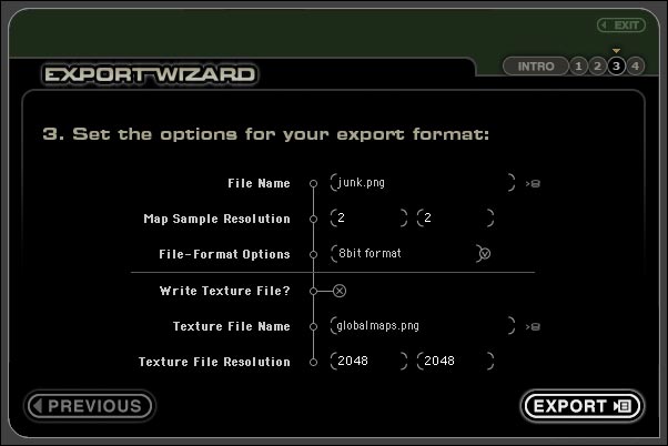
It's the texture files we'll use to create the map. Although it'll take a long time, the higher resolution that you can use, the better. For the , I used 1024 on a side. A size of 512 is a good test size. Some concrete numbers here - assuming the default Mojo planet radius of 6,000,000 meters and a map made up of faces 1024 on a side, the final map has a resolution of approximately 9 kilometers per pixel!
NOTE! It can take a _long_ time to export the planet texture maps! I think it was about half an hour to export the panels for the large map, YMMV.
Once you export, you'll have 6 tiny heightfield files that you can throw out and 6 texturemap panels that are ready to be stitched together in your favorite 2D image editing program. They will be numbered 1 through 6. Where I used the name "globalmaps.png" above, the files I get will be named "globalmaps_1.png" through "globalmaps_6.png".
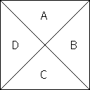
The two polar panels (1 is the north pole, 3 is the south) will need to be cut into four triangular sections. Three of the remaining four panels will need to be rotated when they are stitched into the map.
Here's the key for the polar panels:
and here's the overall plan for where to place the panels:
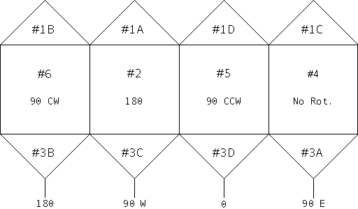
The second row of text in the square panels specifies how to rotate those panels. It should be evident how to rotate the triangular panels. The bottom row shows the longitude values at the points.
A Note about Parameter Bombs
In order to find out where the opening camera shot was on MWv1p1-default, I created a parameter bomb that was 50,000 meters square, colored the inside of it bright pink and then exported my planet texture files at 1024x1024. The parameter bomb showed up as a square only about 4 pixels on a side.
So, if you have small parameter bombs around, they probably won't be terribly obvious on your map. However, if you have large parameter bombs, you'll want to edit the material inside of those bombs in the same way as the global material, starting with the WorldMapLines.mjl, setting your latitude line color as desired and plugging the parameter bomb's material into the appropriate spot. This is only an issue if your parameter bombs are large and cross latitude lines.
MojoWorld Boulders
"PlainBoulder.zip" is now lost media, unless someone still has an archived source somewhere. Although it wouldn't be hard to create your own "plain boulder".
"shapeblend-minimum.png" is now lost media, unless someone saved a copy of the image.
"randomnode1.gif" is now lost media, unless someone saved a copy of the image.
"random1.png" is now lost media, unless someone saved a copy of the image.
How to create a new boulder, and for Pro users, how to add randomizations to those boulders. (Std / Pro)
by Calyxa Omphalos
Introduction
Boulders and rocks are a new feature in MojoWorld 3. This tutorial shows you how to create and use them.
Making new boulders can be done by starting with any other boulder in the library, but this tutorial will start with a plain boulder object [download PlainBoulder.zip] which has no material and no displacement texture. The current version of the boulder tool does not use the material's displacement parameter to shape the boulder. All of a boulder's shaping comes solely from the boulder's surface (as opposed to material) displacement parameter. In the plans for the future is an updated boulder tool that will use both its own displacement as well as the material displacement for determining the shape. When this type of boulder becomes available, boulders will be much like planets, in that they will be able to have true overhangs!
"Installation"
Place the downloaded and unzipped PlainBoulder.mjl file into the Boulders folder inside of the Libraries folder in your MojoWorld 3 installation. The next time you launch MojoWorld, click the boulder icon and then double-click the plain boulder object in the library importer dialog to create a new plain boulder object. Drag in the RTR to place the plain boulder.
A word about Object Size
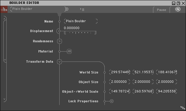
Click the boulder hot button to open the boulder editor. Expand the Transform Data control stack. The thing to note in the Transform Data is the Object Size. A boulder's internal size is always 2 meters by 2 meters by 2 meters. In the following screenshot, the plain boulder has been re-scaled in the RTR along two different sides using the scale tool. While the X, Y and Z values in the World Size parameter are all three different, the X, Y and Z values for the boulder in Object Size are all 2. The significance of this will become clear when we create the boulder's shape using a texture on the boulder's Displacement parameter.
Assign a Plain Material
Before we get into shaping the boulder, assign a plain grey material to the boulder by clicking the circle-M and then choosing 'New Material' from the material editor's menu. Close the material editor for now. With this plain grey material on the boulder, test renders of the shape textures will show much more detail.
Defining the base shape
Back in the boulder editor, click the semi-circle next to the Displacement parameter and choose 'Texture.' In the texture editor which opens, choose 'New Texture' from the menu. Change the texture's name to 'Boulder Shape'. Click the first circle-T to enable the first texture leaf. Change the texture leaf's name to 'Base Shape'. Click the leaf again to expand its kickstand. Change the Monofractal to Noise, as this texture leaf will be creating a simple underlying shape for the boulder. More complex shaping will be added with a second texture leaf later.
At the tail end of the kickstand, change the input coordinate to Object Position. The reason to define this texture in Object Position instead of World Position is so that the boulder maintains its shape regardless of where it is located in the world. The scaling of this texture will now be relative to the object's internal size, which we've seen is always a constant 2 meters for boulders. This means that the default Largest Feature Size value of 1000 on the Noise is way too large. In exactly the same way that the Largest Feature Size of a texture applied to the planet shouldn't be much larger than the planet's diameter, the Largest Feature Size of the texture used to shape the boulder shouldn't be much larger than the boulder's diameter. Set the Noise's Largest Feature Size to 1.0.
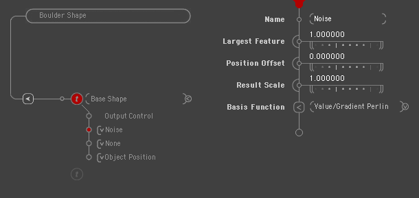
Also much like creating the mountains on the planet, the boulder's displacement needs to have its Result Scale increased. Just how much to increase it depends on the size of the boulder. We'll create a texture that'll make the Result Scale on the boulder's base shape stay proportional to the size of the boulder itself so that we don't have to worry about re-setting the parameter's value after re-sizing the boulder object.
Click the semi-circle next to the Result Scale parameter and choose 'Texture'. In the new texture editor which opens, choose 'New Texture' from the menu. Change the texture's name to 'Result Scale Amount'. Click the first texture leaf to enable it and then click it again to expand the texture leaf's kickstand. Change the texture leaf's name to 'One fifth of smallest edge' and then change the Monofractal to 'None'. Change the input coordinate to Object Size. The default parameters on the Object Size node cause it to output the length of the smallest edge of the boulder in World space. This will be a bit too large for our purposes, so open the Input Curve in the Output Controls of the texture leaf and change the Max Output from 1.0 to 0.2. The texture leaf kickstand is shown as an inset for a reminder:
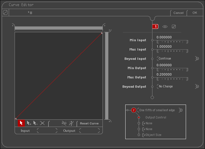
The end result of this texture leaf will be to output a value that is one fifth the amount of the boulder's shortest edge - a perfect value for the Result Scale of the main boulder shape noise texture leaf. Close this texture editor.
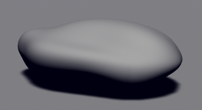
The boulder with only the Base Shape texture leaf now looks something like this:
Defining detail shape features
In the 'Boulder Shape' texture editor, click the second circle T to create a second texture leaf. Name this leaf 'Detail Shape'. The blend between these two leaves is set to 'Maximum' by default. Change it to 'Add' for now, but after the texture for the detail shape leaf is completed, you may want to come back and try some different blends here.
The input coordinate we'll use for the detail shape texture leaf is BoundingBox Pos. This coordinate system goes from 0 to 1 across the bounding box of the object. The special feature of BoundingBox Pos which makes it very useful for the detail texturing on boulders is the De-Stretch Mode parameter, which allows the underlying basis shapes to be applied without distortions.
A De-Stretch Mode Detour
These next three images show a boulder object with no displacement and just a simple color texture. The first is with the De-Stretch Mode set to None:
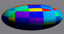
Note that the squares of the texture have been stretched into rectangles, because the underlying boulder object has been stretched from its natural spherical shape into an ovoid shape.
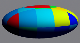
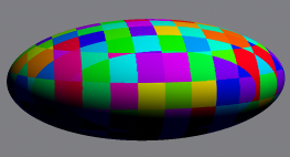
These second two images are with the De-Stretch Mode parameter set to Longest Side and Shortest Side, respectively. The squares of the color noise texture now are truly square, no longer affected by the deformation of the underlying boulder object - the texture has been "de-stretched" so that deformations of the underlying object do not affect the scaling of the texture features.
Finish the Detail Shape texture leaf
For our Detail Shape texture leaf, besides changing the input coordinate to BoundingBox Pos, change the Largest Feature Size on the Monofractal to 0.5 and set its Result Scale parameter to a texture. In the texture editor which opens for the Result Scale, rather than defining a new texture, simply choose the previously defined 'Result Scale Amount' texture from the DDLB in the upper left corner of the texture editor. Close this texture editor for the Result Scale texture.
The boulder now has a base shape and a detail shape adding together to look something like this:
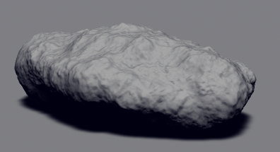
Playing with the blend
Here are four more renders of the boulder so far where the only difference is the setting of the blend between the base shape and detail shape texture leaves. The first is a minimum, then a maximum. The other two are both slope blends, the first has the default curve and the second has a tweaked curve. When the boulder shape is blended by slope, it uses the undisplaced slope of the boulder's underlying spherical surface, oriented to local up. This means that when the boulder is rotated, its shape will change!
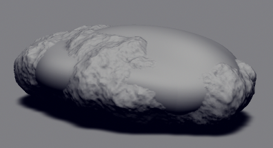
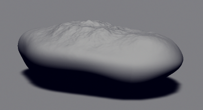
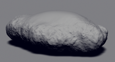
If the boulder's shape is blended by altitude, it uses the absolute altitude at which the boulder is placed in world space, and again, this means that the boulder will change shape when moved to different altitudes in the world.
In these textures and blends, we've stayed with the default basis function of Variable Value/Gradient Perlin. A great deal of variation can be created by using different basis functions and/or using different fractal types when creating the boulder displacement shape texture.
Adding randomization capabilities with MojoGraph
Because we have not yet built in any randomization capabilities, this boulder will be the same shape even when cloned or told to randomize. To add randomization abilities, you need to have MojoWorld Pro, as the Random node is a MojoGraph feature. We'll put a Random node onto two different parameters as examples - the Largest Feature on the base shape Noise, and the Roughness on the detail shape Monofractal. Any parameter that can be driven with a function graph can have a Random node attached.
Open the 'Base Shape' texture leaf in the texture editor for the boulder's displacement parameter. Select the Noise node. Change the Largest Feature parameter to a Function (note: MojoWorld Standard users will not be able to do these steps.) In the function graph editor, there will be a single brown node for the Largest Feature parameter. Use the 'Create New Node' menu item to open the node list. Choose the Utilities category and then choose the Random Node. Click OK to create the Random Node.
The two parameters of the Random node to worry about are the Position and Variance. The Position parameter can be thought of as "the base value" and it should be set to the same value as the parameter to which the Random node is being attached. In this case, that parameter is the Largest Feature of the Noise defining the base shape of the boulder, 1.0. The Variance parameter is a maximum by which the Position parameter will be changed in each randomization. Setting the Variance to a value of 0.5 will effectively make the random range anywhere from 0.5 to 1.5.
The last parameter on the Random node, Sigma, is a drop-down list box. The choices here affect how "clustered" the randomizations are. When set to Uniform, the randomizations are evenly spread across the range defined by the Variance and Position parameters. Choices further down the menu essentially tighten up this range. Close the function graph editor.
Open the kickstand for the detail shape texture leaf and select the Monofractal node. Change the Roughness parameter to Function. Create another Random node. Set the Position parameter to 0.375, equal to the Roughness parameter before it was changed to a function. Set the Variance parameter to 0.1 which effectively limits the range of random possible values to be between 0.275 and 0.475.
Each of the Random nodes has its own Randomize punch button. Clicking the punch button here will cause that particular random node to choose a new value. When the Randomize punch button inside of the Boulder editor is clicked, then all Random nodes attached to that boulder are told to choose new values. These three renders show different randomized versions of the boulder so far:
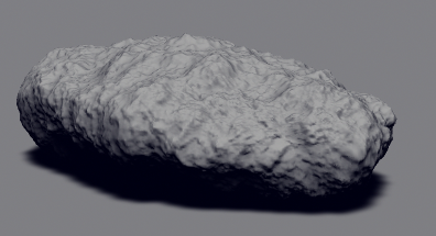
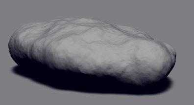
Coloring the boulder
With the displacement texture defining the shape of the boulder, we took great pains to define that texture in terms of the boulder's space so that the boulder would not change shape when relocated. This issue also impacts the color texture, but for many color textures, it'll be far less noticeable that the boulder changes color when moved than a shape change.
For boulders with a very complex underlying texture, it's best to keep the diffuse color of the material quite simple, as a complex diffuse color texture will hide the details of the boulder's shape.
Slope-driven color textures applied to the boulder will use the slope of the boulder's surface after it has been modified by the displacement texture on the boulder. This is different from when slope is used in defining the displacement texture itself, which uses the slope of the underlying boulder sphere as oriented in world space.
If you are creating your boulder to integrate into a specific planet file, you may want to use a color texture that is also used in your planet's land material, but keep in mind the caveats above regarding the boulder's color changing as it is moved around the world. Unless you're making an animation and causing the boulder to move, though, it probably won't matter.
Randomizing colors on boulders
The easiest way to set up random colors for boulders goes right along with the suggestion that the diffuse color be kept simple. Starting with the plain grey material put onto the boulder as one of the first steps in this tutorial, click the semi-circle next to the diffuse color parameter and change it to a function. In the function graph editor which opens, create a Texture Color Control node (found in the Utilities category) and connect it to the brown Diffuse parameter node. Then create a Random Node and connect it to the Texture Color Control node. In the Texture Color Control node, the only changes to worry about are in the Gradient. Edit the gradient to include the various different solid colors you'd like your boulder to use.
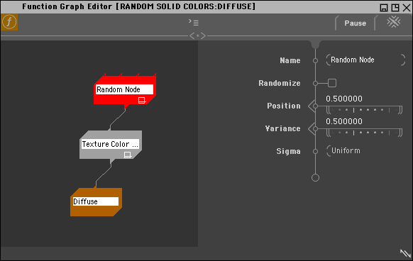
In the Random Node, set the Position parameter to 0.5. This corresponds to the color at the center of the gradient. Set the Variance parameter to 0.5 as well. This allows the output of the Random Node to vary between 0.0 and 1.0, which will cover the full range of the gradient.
The completed Tutorial Boulder [download TutorialBoulder.zip] is set up with a constant, but random coloring using this method.
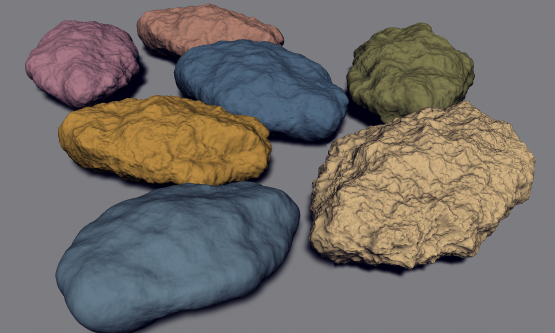
A collection of random boulders stamped from the completed tutorial boulder.
Crater Your MojoWorlds
"landeditor.gif" is now lost media, unless someone saved a copy of the image.
"centretexture.png" is now lost media, unless someone saved a copy of the image.
"pbomb-editor.gif" is now lost media, unless someone saved a copy of the image.
"crater-inside-bomb.png" is now lost media, unless someone saved a copy of the image.
How to use the MojoGraph 'Crater' Node and a Parameter Bomb to create craters on your MojoWorlds (Pro Only!)
by Calyxa Omphalos
Introduction
This tutorial discusses the Crater Node, a MojoGraph function node. The Crater node has been a part of MojoWorld since the pre-alpha of version 1.0-no kidding!-but it has lived in relative obscurity, buried in the Utilities category in the Create Node dialog in the MojoGraph interface (formerly known as the Pro UI). While it is possible to approximate some of the results of this tutorial using the Response Curve on a Parameter Bomb, using a Crater Node allows for far more flexibility.
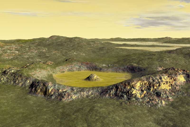
Unlike the render above, most of the sample renders in this tutorial show the Crater Node used on an empty flat grey planet. This is so that the details do not get lost in the noise of an interesting planet, as well as simplifying the crater creation for the purposes of the tutorial. Later in the tutorial, integrating a crater into an already-developed planet will be covered.
A First Look
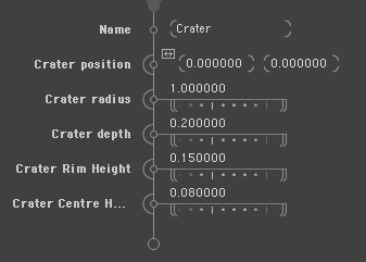
The first parameter of the Crater Node is the 'Crater position' parameter. This determines where the crater is located on the planet, as well as a base reference for the crater's size. It requires a PBomb Position node as its input.
Normally when shaping the terrain inside of a Parameter Bomb, a land texture editor specific to that PBomb is opened via the Land Texture hot button displayed when the PBomb is selected. When using the Crater Node, it can be easier to integrate the node directly into the Mountain Height function graph. This is because of the PBomb Response Curve. The default Response Curve on a PBomb causes the crater shape to be obscured by the blending. This effect will will be revisited later in this tutorial.
Getting Started
For now, start with File→New and then create a circle parameter bomb. While the Crater node will create a circular crater even when used with a square PBomb, using a circle PBomb works better for visualization and for material blending. Make a note of the radius of the PBomb and then click on the planet to de-select the parameter bomb and activate the global parameters hot buttons.
Open the Land Editor (the Mountain icon, not the circle-T Land Texture Editor) and change the Mountain Height parameter to a Function.
The graph editor will contain a single brown node labeled 'Mountain Height'. Build a graph as follows:
- Create an Add node and connect it to the Mountain Height node. This will allow for the rest of the planet's land texture to be attached to the Add2 parameter later.
- Create a Curve node and connect it to the Add1 parameter of the Add node. This will multiply the output of the Crater node from its -1 to 1 range to a range that is more suitable for adding into the final terrain.
- Create the actual Crater Node. It is found in the Utilities category. Connect the output of the Crater node to the input of the Curve node.
- Create a PBomb Position node. Connect that to the Position parameter of the Crater node.
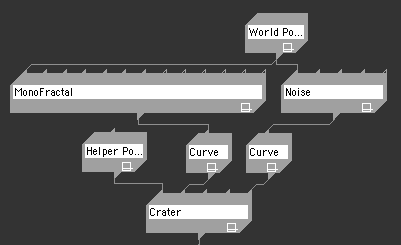
The graph should now look like this:
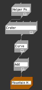
In order to see the results in the RTR, two more things must be done. First, in the PBomb Position node (labeled 'Helper Po...' in the screenshot above), select the parameter bomb in the drop-down list box. Then, edit the Max Output in the Curve node. A good value to start with for the Max Output is about 1/4 of the diameter of the parameter bomb. Here, the parameter bomb has a diameter of 1359.01 meters and the Max Output value on the Curve is set to 300 meters:
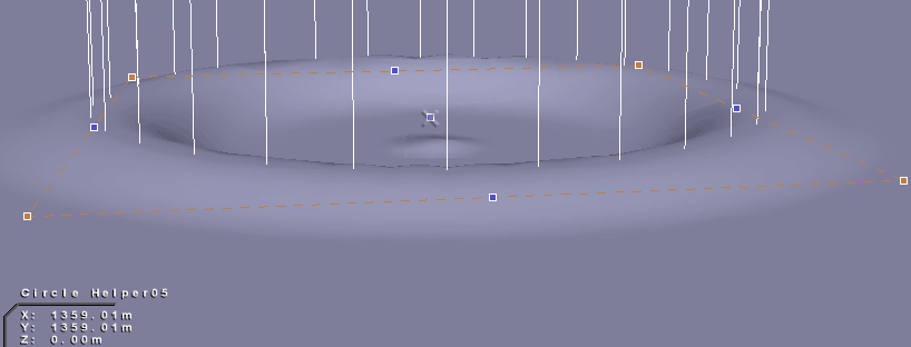
Note that the 'fence' of the parameter bomb protrudes from the top of the crater's rim. This will be important to consider if the crater is built inside of the parameter bomb's land texture editor instead of as the tutorial shows so far, as part of the planet's Mountain Height function.
Gettin' Jiggy With It
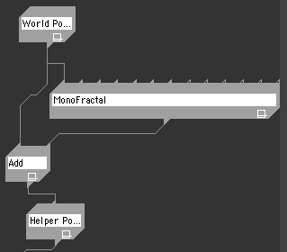
So far, the crater looks very smooth and uninteresting. One way to make the crater more interesting is to add some domain distortion. The PBomb Position node at the top of the current graph has an input parameter but as of yet has nothing attached to it. When this node has no function node as input, it defaults to the World Position, regardless of any constant value that may be specified. To add domain distortion, create three more nodes as follows:
- Create an Add node and connect it to the input of the PBomb Position node.
- Create a fractal node and connect it to the Add2 parameter of the Add node. This tutorial uses a Monofractal node, but any fractal node can be used.
- Create a World Position node and connect it to both the Add1 parameter of the Add node, and to the Position node of the fractal node.
The top of the graph will now look like this:
Before the domain distortion will be effective, there are a few more parameters to modify in the fractal node. First is the Largest Feature size. A good starting value is about the same value used for the Max Output on the curve, around 1/4 of the PBomb's diameter. When editing the Largest Feature in the function graph editor, the value has more than one field, in fact, there's a field for each dimension of the fractal. For now, set all three fields to the same value, but later on, try tweaking them with different values. Next is the Result Scale. A good starting value is around half of the value used for the Largest Feature size. Lastly is the Basis Function. When fractal nodes are created in MojoGraph, they are created with the Basis Function set to 'None'. Any Basis Function other than 'None' will do. This next render uses a Largest Feature size of 300, a Result Scale of 150 and the Gradient Perlin Basis Function:
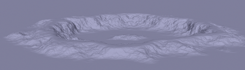
This type of distortion affects the whole crater. A different way to distort the crater is to drive the other parameters of the Crater Node with functions.
Driving Crater Parameters with Functions
Reconfigure the graph by disconnecting the domain distortion at the output of the Add node, create a Curve node, and run the output of the fractal through the curve and into one of the other Crater parameters, in this case, the Crater Radius. Things are a bit out of control right now, so there are a few more parameters to tweak.
First is that the Result Scale on the fractal node was set to 150, but the Crater Radius parameter expects values close to 1, so set the Result Scale back to 1. The Crater is still not recognizable at this point, because while the Radius parameter is expecting a value close to 1, it's being fed values ranging between -1 and 1. Open the Curve Editor on the Curve node and set the Min Input to -1, leave the Max Input set at 1, and then set the Min Output to 0.8 and the Max Output to 1.2. This will feed values roughly between 0.8 and 1.2 into the Crater Radius parameter, resulting in a crater that looks something like this:
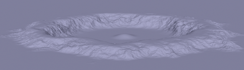
In many ways, this is very similar to the domain distorted crater, but only the radius has been affected. Note how the bump in the center of the Crater is still very smooth. Unlike with the domain distortion technique, the center bump can now be shaped with an entirely different function.
Create another fractal node and another Curve node. Connect the World Position node to the fractal node's Position parameter, then connect the output of the fractal node to the input of the Curve. Then attach the output of the Curve to the Crater Centre Height parameter.
The default value for the Crater Centre Height parameter is 0.08, so in the Curve Editor, the Min Output and Max Output should be set up to create a range similar to this value. As with most fractal nodes, the Input range will be from -1 to 1, so set the Min Input to -1 and leave the Max Input at 1. Also remember to set the Basis Function in the fractal to something other than 'None' and lastly, set the Largest Feature parameter of the fractal.
In this next render, the fractal used is a simple Noise, the Basis Function is Voronoi (1st and 2nd closest neighbor mode), and the Largest Feature is set to 23. The Min Output and Max Output in the Curve node are set to 0.1 and 0.2, respectively. This creates a higher center than the default constant of 0.08 as well as giving it a texture.
The graph for this Crater now looks like this:
Experiment by driving the other Crater Node parameters with functions. The procedure of using a Curve node to limit the output of various fractal nodes to a range close to the default value of the parameter being driven applies to all the parameters of the Crater node.
A brief note about the Crater Depth parameter - while this parameter is a positive value, it represents the amount below 0 that the bottom of the crater is depressed.
The Parameter Bomb Parameters
Open the Object List and click on the Circle Helper object ('Helper' is another name for PBomb) to select it. The Hot Buttons area now refer to the area inside of the PBomb. Click the circle-M associated with the Land Material. The material editor which opens will be completely empty. Use the menu to create a new material. Then, for the purposes of visualization only, set the diffuse color of the plain material to something like a bright pink. The result is something like this:
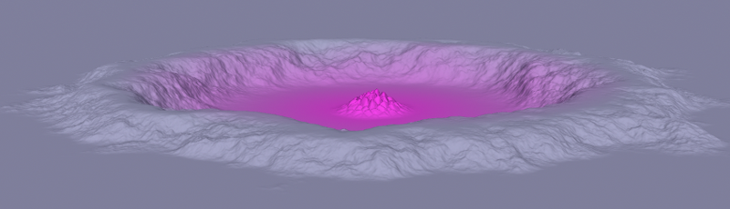
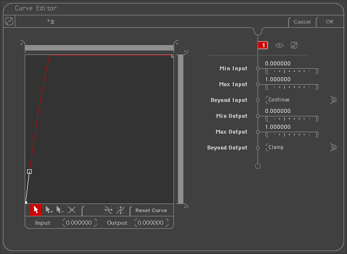
What's most important about this example is that only the very center of the PBomb is the fully saturated pink from the material assigned to the PBomb. This is because of the PBomb Response Curve, found in the Parameter Bomb Editor. Click the hot button at the top of the stack which has the same icon as the circle Parameter Bomb object to open the Parameter Bomb editor and access the Response Curve:
Change the Beyond Output DDLB to 'Clamp'. Click the upper-right point and set its control handle horizontal. Click the lower-left control point and angle its handle upwards. This is where the Beyond Output 'Clamp' comes into play - as the lower-left handle is moved upwards, the curve flattens out against the top of the curve editing area.
Using the Parameter Bomb Land Texture Editor
Even with this curve, defining the crater inside of the parameter bomb's land texture editor has a very different effect than defining the crater as part of the Mountain Height function directly. For this next image, the Mountain Height function has had the bottom-most curve node disconnected from the Add1 parameter of the Add node attached to the Mountain Height parameter node. This removes the crater from the Mountain Height function. Rename that Curve node to a name that can be easily found in the main node list. In the Land Texture editor associated with the parameter bomb, create a new texture. Enable the first texture leaf and then convert it to a function. In the function graph editor, disconnect the Texture Color Control node from the brown Main Value parameter node. Use the 'Import from other Graph' menu item to import the Curve node from the original Mountain Height graph, and connect it to the Main Value parameter node. Now the crater shape is defined within the parameter bomb and the resulting shape looks like this:
Not only is it a very different look to the Crater, setting up the Crater node function graph inside of the Parameter Bomb's Land Texture Editor has another pitfall. With the Add node structure integrated into the main Mountain Height function, the crater will conform to the rest of the planet's terrain. When created separately inside of the Parameter Bomb's Land Texture Editor, the resulting crater may end up many meters or even kilometers above or below the surrounding terrain, since the output of the Crater node function is in absolute elevation values, rather than relative ones. This can be adjusted by adding a constant to offset the crater down or up to the level of the surrounding terrain.
There are two more changes that can be made in the Parameter Bomb editor to allow the crater shape to be defined within the PBomb and not be as truncated by the PBomb Response curve. First is the 'Keep in Circle' checkbox. This will need to be unchecked. The other change to make to allow the crater to extend beyond the PBomb's fence is to set the Min Input of the Response Curve to a negative value. When set to -1, the PBomb Response Curve begins its effect one PBomb radius outside of the PBomb's fence.
Integrating a Crater in an Established World
In general, a crater will look more natural on a relatively flat area. After locating where to put the crater and creating the Circle Parameter Bomb, use the Land Editor to change the existing Mountain Height to a function, if it is not already a function.
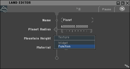
Once the entire Mountain Height texture has been changed to a function, open the function graph editor. Depending on whether the terrain was previously defined only as a Generator texture, or if it had function graph components, the graph may need to be re-laid out using the Auto-layout menu item. Once the graph is organized, create an Add node and connect it directly to the brown Mountain Height parameter node. Then connect the bottom-most node on the original terrain function graph to the Add2 parameter of the Add node. Click on the collapse icon on that node to make room in the graph editor, if needed.
Other than the detail of changing the entire Mountain Height to a function graph, all of the information about creating and using a crater has been covered above, with the exception of a minor bug with textures converted to function graphs....
A Known Bug With Functions
The following examples are taken from the planet file Southern Parfait, which can be found in the Planets folder in the Libraries shipped with MojoWorld 3. This first screenshot is the Land Texture editor for the Mountain Height texture before it has been converted to a function graph:
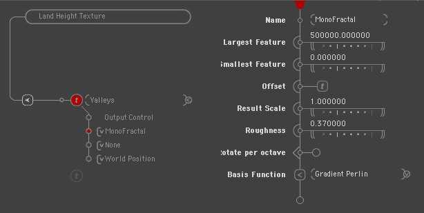
The point to notice is that the Offset parameter has a texture attached. Now here is a screenshot of this same Mountain Height, converted to a function graph:
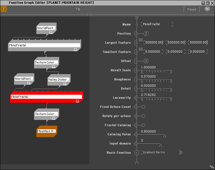
The point to notice here is that there is still a circle-T icon attached to the Offset parameter of the Monofractal node. This is a Bad Thing™ because it's possible to edit the function graph above the node labeled 'Valley Distort...' to a configuration that does not fit into a Generator texture editor, but the Generator texture editor can still be invoked by clicking on this circle-T, causing a crash.
Whenever converting a Generator texture into a function, never click on a circle-T icon when it is displayed in the parameter list, but rather, disconnect the node above, delete that node, and then connect the output of the remaining node back to the parameter in question. For example, in the graph above, the 'Valley Distor...' node would be deleted and the 'Texture Color ...' node above would then be connected to the Offset parameter of the Monofractal, thus removing the circle-T and replacing it with a circle-F. The extraneous node will have the same name as the texture's name, in this case, 'Valley Distor...' or in the case of a texture with a default name, 'Main Texture ...'
Also note that clicking the semi-circle next to any parameter brings up the choices of Texture and Function. Choosing Texture for this will lead into the same trap, so it's recommended that when working in a function graph editor, always create nodes using the Create Node menu item and never use the semi-circle menu on any parameters.
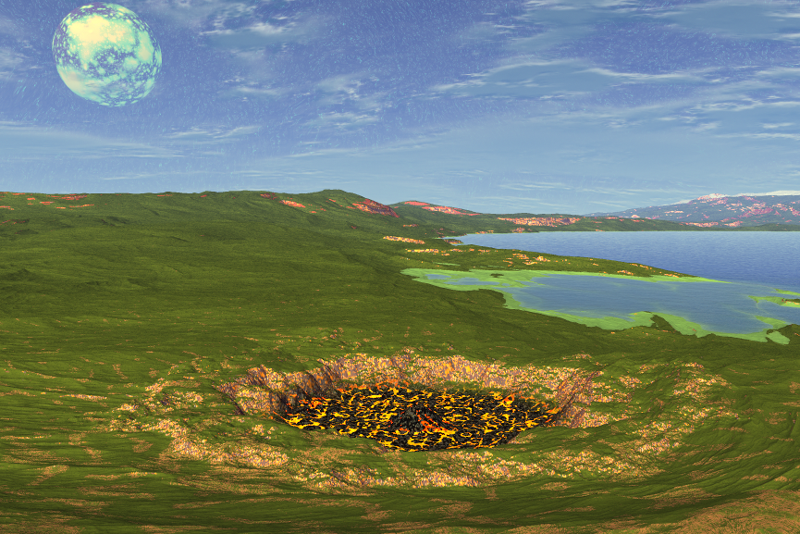
Lastly, here's a render of the crater created on Southern Parfait:
Distributed Rendering
It does not appear any of the images survived capture, therefore they are omitted.
How to use the Uplink Queue to parcel out large render jobs to multiple processors (Std and Pro)
MojoWorld 3.1 does not include a direct interface for distributed rendering, but you can use MojoWorld's Uplink Queue and Render Room to manually parcel out jobs which can then be rendered on different machines, or a second processor within the same machine.
For MojoWorld to make full use of the multiple processors on a single machine, one must launch multiple instances of the MojoWorld application, one for each processor.
On multi-processor Windows machines, double-click the MojoWorld icon to launch one instance of the application, and then double-click the MojoWorld icon a second time to launch a second instance. The Macintosh OS prevents multiple instances from running, and double-clicking an application's icon while the application is already running only brings the one instance to the foreground. To run multiple instances of MojoWorld on a Macintosh, you will need to duplicate the MojoWorld application icon and give it a different name, i.e., MojoWorld-instance1. Repeat for each processor in the machine, then launch multiple instances of MojoWorld by double-clicking each of the icon copies.
Distributed Rendering for a Still Image
To distribute the rendering of a single still image across multiple MojoWorld instances requires using the Tiled Rendering option of the Uplink Queue.
Create your world, select your view, and then use the 'Process Later...' menu item on the Render Settings Menu. This will open the Uplink Queue dialog. When the job is selected in the top Queue portion of the dialog, the lower portion shows the render settings associated with that job. All settings for the render job can be edited here.
The following diagram of the Uplink Queue editor has been trimmed down for conciseness. The dashed lines indicate where parameters have been trimmed out. The parameters most important to Tiled Rendering are the last four of the Advanced Settings menu expander.
When setting up the initial render queue job, set up all the render parameters that must be the same in all of the jobs. These parameters include the various quality settings, the pixel dimensions, and so forth. Basically every parameter except for the 4 tile options.
Save the world file. This render queue job will be cloned after the file is copied to other machines participating in the render.
Copy the world file over to all machines participating in the render. On each machine, open MojoWorld and open the local copy of the world file.
Go into the Uplink Queue editor and make a clone of the render job. Open the Render Settings→Advanced Settings control stack. Set the Start Tile and End Tile of the job to render the desired range of tiles.
Tile ranges are calculated based on the pixel dimensions of the final render and on the tile size.
For example, a still image whose final size is 2000 x 1000, using a tile size of 500 (x 500 pixels, tile size is in square pixels) will result in 8 tiles total, 2 rows of 4 tiles each. MojoWorld instance 1 can render tiles 0 through 3, MojoWorld instance 2 can render tiles 4 through 7.
Important! Because file pathnames are not portable across machines, after adjusting the Start Tile and End Tile parameters, be sure to click on the 'Save to Disk' icon up in the Queue portion of the dialog. This will bring up a File→Save dialog in which you can specify the file name and destination folder.
Important! Be sure to disable the original uplink queue job so that it does not process when the render room is started.
When rendering is distributed across multiple machines, the final image may be assembled in two different ways. The first way is to put all of the files into a single folder on a single machine. Start a MojoWorld instance on that machine and render the one fastest tile. When that one tile completes, MojoWorld will assemble all of the tiles into the final image. The other way is to combine the files using Photoshop or other similar image editing software. Tiles should be loaded into individual layers placed over the main image file. Blend the layers with Maximum as the blank spaces in the main image file will be black.
Distributed Rendering for an Animation / Still Frames
Create your world, record some time in the Movie Editor, and then use the 'Process Later...' menu item on the Movie Editor Menu. This will open the Uplink Queue dialog. When the job is selected in the top Queue portion of the dialog, the lower portion shows the render settings associated with that job.
Copy the world file over to all machines participating in the render. On each machine, open MojoWorld and open the local copy of the world file.
Go into the Uplink Queue editor and make a clone of the render job. Open the Render Settings→Movie Settings control stack. Set the Start Frame and End Frame of the job to render the desired frame range.
Important! Be sure to click on the 'Save to Disk' icon for the destination file name of the render queue job clone. This is important to set not only the file name and destination folder, but also to set the file type to a still frame format such as PNG. Rendering animations in a distributed fashion requires that the sections be rendered as still frame sequences and then final composition into a movie will be done with the video editor of your choice.
Processing the Uplink Queue
After the Uplink Queue job clone has been modified to specify the tile range or frame range to render, click on the Render button in the upper right corner of the Uplink Queue dialog.
MojoWorld will enter the Render Room interface. Make a final check of the queue and then click on the Render button in the Render Room to start the queue process.
Bryce Into Mojo
How to import terrain data from Bryce 5 into MojoWorld. Also covers some issues of taking Mojo terrain data into Bryce (Std / Pro)
Introduction
This tutorial will cover exporting terrain and image map information from Bryce 5 and importing it into MojoWorld 3 Standard/Professional. This image is a Bryce render of a terrain and diffuse coloring that will be used in this tutorial:
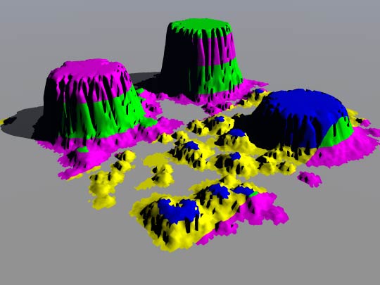
Bryce 5 Export - Terrain Data
Open a Bryce 5 file and select a single textured terrain object. Terrain export in Bryce can be accessed in two different locations. One is via the Export Object... menu item on the File menu. This menu item will only be active if a single terrain object is selected. The other is an Export... option on the pull-out menu located in the upper right corner of the Terrain Canvas palette in the Terrain Editor.
After choosing either of those export options, an OS-specific file dialog will open. This dialog has a menu from which a variety of formats can be chosen. Only two formats on this menu are suitable for creating terrain data which can be imported into a MojoWorld parameter bomb: PGM and USGS DEM.
Choose one of these two formats, select a file name and click OK. Note that on the Macintosh platform, the three letter extension must be specified for MojoWorld to correctly recognize the file. Each format has its own quirks.
The USGS DEM format imports into MojoWorld without any editing required, however any texture maps will need to be rotated 90 degrees.
PGM import into MojoWorld 2.0/3.0 is subject to a small known bug which can be worked around with a text editor. When a PGM is exported from Bryce, it includes a few comment lines. MojoWorld will appear to import the PGM data, but the area inside of the Parameter Bomb will be flat. This is because MojoWorld 2.0/3.0 does not correctly deal with the comment lines and assumes 0 for all points in the PGM. This can be fixed by editing the PGM data file in a text editor before importing into MojoWorld. The top few lines of the file will look something like this:
P2
# Generated by Bryce5
# Brought to you by the letters R&D; - MetaCreations, Corp.
256 256
65535
841 843 845 847 849 851 853 855 857 859 861 863 866 868 870 872
Delete the lines which begin with a # sign and save the file. It will now correctly import into a MojoWorld Parameter Bomb.
Another alternative for getting terrain data out of Bryce and into MojoWorld is as a greyscale heightmap. In the Bryce Terrain Editor, use the keyboard shortcut for Copy (ctrl-C on Windows; command-C on Macintosh). Then, open an image editing program, create a new document and use the keyboard shortcut for Paste (ctrl/cmd-V). Save this document as one of these image formats: PNG, TIF, BMP, JPG. Saving as a greyscale heightmap does not have as much vertical resolution as using one of the digital terrain formats previously discussed.
Here is the heightmap. Note that the render at the top of this tutorial, and subsequent renders of this terrain will have the viewpoint located in the upper left corner looking at the tall tower in the lower right corner.
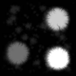
Bryce 5 Export - Texture Map Data
A second export needs to be done from Bryce to get the texture map data. Bryce only generates texture maps when it is exporting to one of the Mesh Formats. This ends up creating not only the image maps, but also an extra mesh object of the Bryce terrain that can be imported as a 3d model. This model cannot be used as terrain data inside of the MojoWorld Parameter Bomb.
Initiate a terrain export in Bryce to bring up the OS-specific export dialog. Choose the Wavefront OBJ format from the format menu. Although any format marked as a (Mesh Export) will open the Bryce Terrain Export room (as opposed to directly exporting terrain data, as it did for the DEM export), only the Wavefront OBJ export puts the texture maps in the correct orientation. Many of the other formats create images maps that are inverted vertically, and some of the Mesh Export formats do not export the image maps at all!
The only texture map which will be automatically applied by the MojoWorld terrain import is the Diffusion Color map. Other maps may be generated by the Bryce Terrain Export dialog. Those which are shown as available on the list will depend on the material properties of the material applied to the terrain.
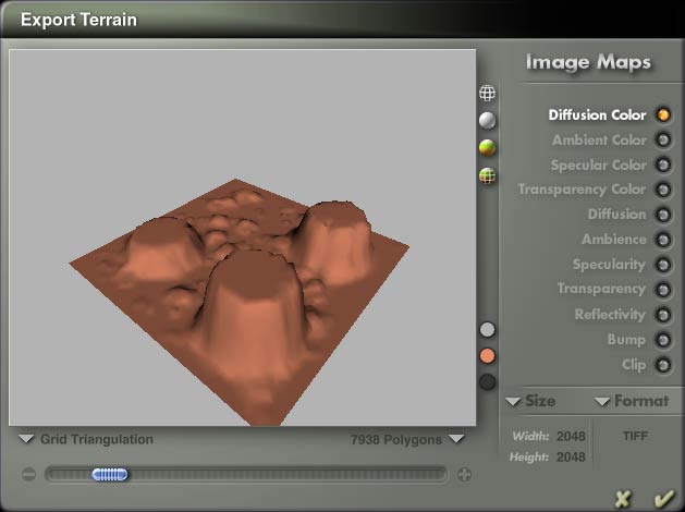
Each texture map file will append a descriptive string, such as "diffcol" for the Diffusion Color map, and "bumpamt" for the Bump map. On Windows, all the exported files have their proper three letter extension. On Macintosh, these extensions must be added manually for MojoWorld to correctly parse the files.
The default format is a highly compressed JPG, so choosing either BMP on Windows or TIF on Macintosh is recommended. Note that on the mac, it'll be necessary to append .tif to the image maps for MojoWorld to correctly recognize them.
Here is the Diffusion Color map.
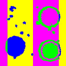
MojoWorld 3 Import
In order for the terrain data to be seamlessly integrated into the planet's skin, it is imported into a Parameter Bomb. Due to quirks in the various formats and the way the exports come out of Bryce, some may need additional adjustments after the importing process.
Create either a square or round Parameter Bomb. The square corners of the terrain data and texture map(s) will be truncated if used in a round Parameter Bomb.
There are two places where the Terrain Import can be accessed in MojoWorld. The first is Import Terrain... option on the File menu, which opens the Terrain Import Wizard, starting at the Intro screen. The second is the Import Terrain... option on the Parameter Bomb Options menu located in the Parameter Bomb editor, which opens the Terrain Import Wizard, starting on screen #2.
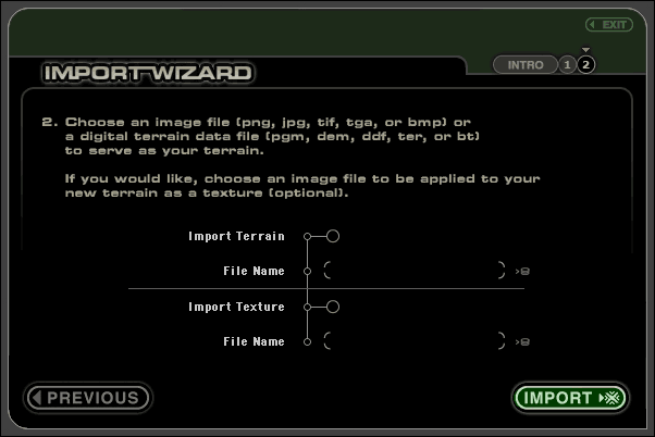
The first field is for the terrain data (the DEM, PGM or greyscale heightmap file). The second field is for the diffuse color texture map. Once both fields have been specified, click on Import. The import process will automatically create a terrain texture and a material with a diffuse color texture inside of the selected Parameter Bomb.
The Land Shape Texture
With the Parameter Bomb selected, click the circle-T icon to open the texture editor for the land inside of the Parameter Bomb. The following texture will have been automatically created.
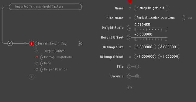
Parameters to note here are:
- Height Scale - the height scale is calculated automatically by the import process. Its value will depend on the size of the Parameter Bomb and on the data in the bitmap itself. Use this control to vertically scale the terrain within the Parameter Bomb.
- Height Offset - this value corresponds to the elevation of the terrain at the initial mouse-down point used to create the Parameter Bomb. Use this control to raise or lower the whole terrain unit relative to the surface of the planet outside of the Parameter Bomb.
More texture leaves can be added in this texture editor to add procedural detail to the bitmap terrain. Before adding a new texture leaf, note the size of the Parameter Bomb. The Largest Feature Size of any fractal intended to add procedural detail should not be larger than the Parameter Bomb.
The Land Material Diffuse Color Texture
With the Parameter Bomb selected, click the bottom-most circle-M icon to open the material editor for the land inside of the Parameter Bomb. Click the first material leaf to expand it. The Diffuse Color parameter has a texture attached. That color texture looks something like this:
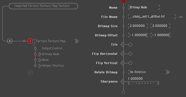
Procedural diffuse color detail may be added in this texture editor, with the same caveats as for adding procedural data to the terrain data - that the Largest Feature Size of any fractals should not be larger than the size of the Parameter Bomb itself.
Parameters in the Bitmap Node that may need editing are the ones related to orientation - Flip Horizontal, Flip Vertical, and the Rotation parameter. Which of these may be needed will depend on the formats of the exports. This is summarized in the following table:
| Data / Format / Export | Orientation of Map inside of Parameter Bomb | Notes |
|---|---|---|
| DEM | 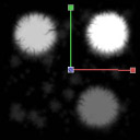 |
All image texture maps will need to be rotated 90 degrees because of the orientation of the terrain data inside of the Parameter Bomb. |
| PGM | 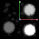 |
The text PGM file must be edited to remove comment lines before import into MojoWorld will work correctly. |
| Image-based heightmaps cut and pasted from the terrain editor and saved with an image editor. | |
Vertical resolution is markedly lower than the digital terrain formats. |
| Image texture maps resulting from exporting the terrain to either .3DS or .DXF | 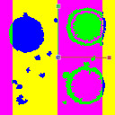 |
A vertical flip is needed in order to align these image maps with the corresponding terrain. |
| Wavefront OBJ | 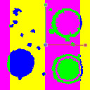 |
This is the recommended export format. |
The Result
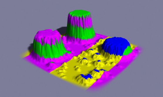
Here's the imported bitmap and color texture map, first in the RTR, then rendered:
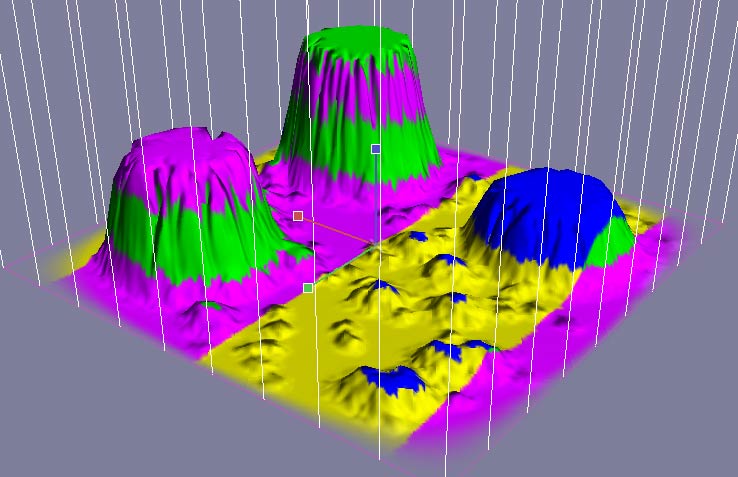
Manually Applying A Texture Map - Bump to Displacement
Because the terrain inside of a Parameter Bomb is part of the planet's surface and not an imported model, using displacements will change the shape of the terrain. This is unlike Bryce, where the bump height acts only as a shadow map.
To use this bump map in the current Parameter Bomb imported terrain, open the land material editor for the material inside of the Parameter Bomb. Change the Displacement parameter from a widget to a texture. In the new texture editor that opens, create a new texture. Name it " Imported Terrain Bump". Click the first circle-T to enable the first texture leaf, then click it again to expand its kickstand. Change the Input Coordinate at the bottom of the kickstand from World Position to Helper Position. Select the current Parameter Bomb on the DDLB to the right. Change the Monofractal to a Bitmap Node.
Several changes are needed in the Bitmap Node's parameters. First is the File Name. Click the Load From Disk icon and select the bump map image file. Change the Bitmap Size from its default of (1, 1) to (2, 2). Change the Bitmap Offset from its default of (0, 0) to (-1, -1). This diagram shows why these two changes are needed - with the default values, the Bitmap would only cover one corner of the Parameter Bomb:
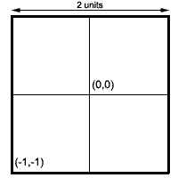
Any rotation or flipping that may have been needed for the diffuse color map will also be needed for the bump map.
Scaling the Displacement
When Bryce exports a bump map, it's as a greyscale image in 256 shades of grey. It treats the mid-tone grey as zero. MojoWorld interprets black as 0 and white as 1. The displacement amount is measured in meters. This allows the displacements to be very accurately scaled in the Input Curve in this texture leaf.
Here is the Input Curve for an example bump map.
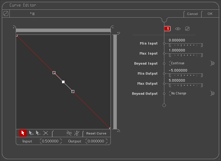
The Min / Max Input values are left at 0 and 1 respectively, as those correspond to black and white in the bitmap node. The center point isn't required, it's just there to show how an input of 0.5 is mapped to 0. The Min and Max Outputs correspond to the amount of displacement, in meters. Negative values push the terrain's surface out and positive values push the terrain in. The curve is inverted so that the white areas of the bump map correspond to pushing the terrain out. The range of -5 to 5 was chosen based on the size of the Parameter Bomb. This particular Parameter Bomb measures approximately 300 meters on a side, so the 10 meter range is around 1/30th of the whole Parameter Bomb. 30 meters would be a suggested maximum for an area of this size.
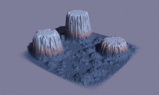
Here's a completed render of the terrain with a different diffuse color map and a bump map:
Horizon Clouds
It does not appear any of the images survived capture, therefore they are omitted.
Use the Camera Location and Dot Product nodes to control effects relative to the current horizon (Pro Only!)
by Hakujin
Here's an easy method to create clouds that are always on the horizon, regardless of camera location. It's a variation on the 'Simple Sky > Sky Color' function graph first seen in Eric DeGiuli's planet, Arak. This technique paints clouds onto the Star Backdrop, which means that any Moons will appear in front of this type of cloud. The same technique can be used to drive a Cloud Layer's Density parameter for horizon clouds that will appear in front of Moons.
The MojoGraph uses a 'Camera Location' node which has been named 'clouds_CameraLocation' in the graph above. This node returns the World Position of the current camera.
The output of the Camera Location node is also subtracted (clouds_Subtract) from a World Position leaf node (clouds_WorldPosition). This results in a vector that points from the center of the planet to a point directly opposite the current camera location.
Both the Camera Location and the Subtract outputs are input to separate 'Set Vector Length' nodes (clouds_wP_SetVecLength and clouds_camLoc_SetVecLength), with the Length parameter values set to '1' ('unit length'). Setting a vector's length to 1 is also known as 'normalizing' a vector.
The outputs from the two Set Vector Length nodes are connected to the two input parameters of a 'Dot Product' math node (clouds_DotProduct). The Dot Product math node compares the two input vectors and outputs a value within a range of '-1 - +1'.
The Dot Product node is comparing two vectors:
A vector that has a length of '1', has its origin at the center of the planet and points to the current Camera Location.
A vector that has a length of '1', has its origin at the center of the planet and points directly opposite the current Camera Location.
Because the two compared vectors are always directly opposed, the Dot Product is always outputting its full value range, '-1 - +1'. We can use that output range to control a wide variety of functions.
In this case, the output from the Dot Product node serves as the input to a Texture Color Control node (clouds_TCC). The output from the TCC node determines the sky color.
An input value of '+1' indicates a point of sky directly above the current camera location and an input value of '-1' indicates a point of sky on the opposite side of the planet. Therefore, an input value of '0' indicates the horizon.
These values are mapped to a color gradient via the TCC Input Curve.
Here are the two gradients that are output in the example renders:
Using the upper gradient example, a white band is created just above the horizon:
Another look at the FG graphic (above) shows the added variation—domain distortion added between the World Position node and the Subtract node. Since the sky is very far away, the various parameters of the Mono Fractal should be rather large:
I used a negative value in the Monofractal's Result Scale parameter simply because I wanted the clouds to look a certain way - you can use a positive value if you prefer.
The resulting render:
By using the second gradient setting (above) we can extend the clouds to below the horizon:
You could also use this FG to drive the density parameter of a cloud layer, make stars that begin some distance above the horizon, etc. Combining it with a Satellite Time > Time of Day node could create some interesting effects.
hakujin
MojoWorld Viewer Quick Start Tutorial
MojoWorld Viewer is a simplified interface for exploring and rendering MojoWorlds. The Viewer is a stand-alone application and is also a room within the MojoWorld Standard and Professional application.
This tutorial assumes that most readers will have entered the Viewer interface from the Generator interface via the File→Go to Viewer menu item of MojoWorld Standard, Professional, or Demo.
First, open a planet to explore with the File→Open using browser... menu item. The screenshots in this tutorial are all taken with the planet Glorious Green.

To look around while you stand in place, drag on the trackball in the center of the JogNav controls in the center of the bottom portion of the RTR (Real-Time Render) window:
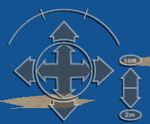
The four flat arrows surrounding the JogNav walk your camera in that direction. The top arrow walks forward, the bottom arrow walks backwards, and the left and right arrows walk to the left and right.
The arc over the top of the JogNav changes your camera's Field of View, while leaving the camera in place.
The vertical double-ended arrow changes your camera's altitude. The targets at the top and bottom end of this arrow will put your camera at fixed altitudes of 10 Kilometers and 2 meters, respectively.
Double-clicking the center trackball will level your camera, which will become a lot more useful when you start flying around and getting the camera tilted at all kinds of crazy angles. However, note that the JogNav is only visible in Walk mode. To fly around, you'll need to learn some keyboard shortcuts for motion.
For our first flight, we'll use the UFO. The UFO works much like the airplane fly mode, except that its speed is relative to its altitude above the planet, and it won't follow the curvature of the planet when you fly out into space.
We'll also record the flight so that you can render a movie.
- Click the 10Km target on the JogNav to be at a nice altitude for starting. Tilt your view down slightly with the trackball.
- Click the UFO icon.
 The JogNav will disappear, so now you'll need to fly with the keyboard and mouse.
- Hit the w key to begin a slow forward motion.
- Hit the r key to begin recording.
- Hit the w key again to speed up a bit.
- As you get close to the surface, gently drag down in the RTR window until you're nearly leveled out.
- Drag gently back up to the point where you first did your click in the RTR window. Don't worry if you didn't get it right—your chances were about zip! Flying is hard and takes lots of practice. UFO mode makes it easier to avoid crashing, because your speed is relative to your altitude.
- When you've lost control or flown far enough, hit the r key again to stop recording.
- Hit the space bar to stop your motion.
- Hit the l key to level the camera out.
- Click on the movie camera icon below the RTR window, towards the right, to open the Movie Editor.

- Click the Go to Start button.

- Click the Play button and replay your animation!
- There's probably a dead interval at the beginning, before you started moving, and some wasted footage at the end, when you lost control. ;-) You can edit those parts out using the calipers at the ends of the timeline.

Now we'll queue up the Movie to render later, and explore some of the render settings:
- Click on the movie camera icon below the middle of the timeline and select Process Later.

- Now you're in the Uplink Queue where you can store rendering jobs for batch processing when you're away from your computer.
- Click the Save icon
 at the lower left. Name your movie file something like “First Zoom.mov”.
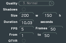
- Choose your settings in the left side of the Uplink Queue. Use some very conservative settings at first: Quality: Normal, Shadows off, Size 200 x 150, FPS such that you don't have too many frames in your movie. It's now in the batch rendering queue. We'll start it rendering after we've had our fun for the day.
- Move to someplace with a decent view, because now we're going to render a picture with MojoWorld's Photorealistic Renderer.
- Click on the Render Settings icon
 below the RTR window and select Low.
- Click on the Camera icon
 to begin your rendering. It will take a while before anything happens on your screen—MojoWorld has to do a lot of work to set up a world before it can start imaging it.
- Click on the Close button
 to dismiss the rendering, or if you like it, on the Save icon.

- Next click on the Crop icon.
 Resize the Crop window that appears in the RTR window by dragging on the upper left and lower right corners. Make your crop window pretty small.
- Now experiment with different Render Quality Settings, selected via the Render Settings icon. Notice that—surprise, surprise—higher quality renderings take longer. For Normal and High quality settings, you may get shadows cast by cloud layers, if there are clouds and if they are set up to cast shadows. These shadows will slow down your renders somewhat. At the Maximum render quality, you'll also get shadows of the terrain onto itself. This type of shadowing takes an especially long time to compute. You can turn shadows on and off in the Uplink Queue. Notice also that rendering goes slowly near the horizon, where there's lots of depth complexity (mountains) for MojoWorld to contend with.
A note about working with MojoWorld and other currently running applications:
- If you ever want to stop MojoWorld from chewing up all your CPU cycles, as for instance when you go check your email, click the Pause button
 beneath the RTR window. You can start MojoWorld up again by clicking the Jump icon
 next to the Pause button.
Changing the planet with the Hyperspace Mixer and saving Settings:
- Now let's change this entire planet using the Hyperspace Mixer on the lower left. The sliders available in the Hyperspace Mixer are created by the author of the original planetary element, so any given planet may have no, one, several or many sliders in the Hyperspace Mixer. These shown here are from the planet Glorious Green:
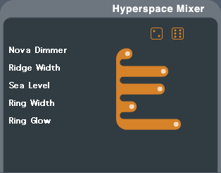
- Click one of the dice and see how they randomize the slider settings. The die with two pips changes them a little; the one with six pips changes them a lot.
- Try changing slider values by hand, by dragging on the white dot on their ends. Note that some sliders, such as the Nova Dimmer slider, will show no effect in the RTR and will show up only when you make a rendering with MojoWorld's Photorealistic Renderer.
- When you have a combination of sliders that yields a world you like, store it by clicking on the Settings Panel icon
 beneath the RTR window.
- Click on the Add Setting
 button to add a new setting. Overwrite the Title and Comments text with whatever you like. Now you can come back to this planet and see your notes reminding you and others why you liked it.
Changing the Time of Day and using the Crop Window:
- Now click the Time icon
 below the RTR window. Drag left or right in the RTR window until you can see the red line that indicates the orbit of the Sun. Depending on what planet you have open, there may also be blue lines in the sky that show the orbits of any moons. The Glorious Green planet has a single moon. All MojoWorld planets have one sun.
- Set up a small crop window there, at the horizon. Now drag the sun icon
 until you see the sun set. Render a little sunset for fun. (The Time of Year control will change the angles of the sun and moon orbits but it won't do much until future versions, when we have entire solar systems in MojoWorld.)
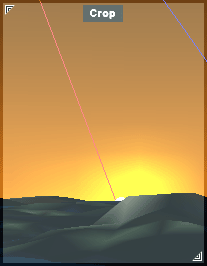
- Let's pretend this is a really memorable scene that we want to save. You can do that by clicking on the Log icon
 that looks like a postcard beneath the RTR window. Click New in the lower right of the Log Editor and add a title and notes just like you did in the Settings Panel. When you have a bunch of Log entries, you can return to any of those places by clicking on the Jump icon beneath the thumbnail image of the entry. Use the Log to record travelogues to share with your friends over the Internet.
Global Navigation and QTVR Panoramas:
- Next let's check out the Nav Panel.
 This provides easy controls for setting the camera orientation, compass direction, field of view, altitude and planetary position. The GPS Globe shows a map of your entire planet. Drag on all the controls in there and have yourself a ball!
- Finally, let's do one of the coolest things you can do in MojoWorld: make a QuickTime VR cubic panorama. Find a nice spot on your MojoWorld, click the Render Settings icon below the RTR window and select Process Later.
- Now you're in the Uplink Queue with a new render job already selected for you. Set Quality to Normal, Size to 512 x 512, and click the circle to the right of QTVR. Select a file name by clicking on the Save icon. Note that the file extension must be .mov for QuickTime VR panoramas-same as for QuickTime movies.
- When you're done for the day, go into the Uplink Queue
 and click Start to begin rendering your saved animation and QTVR panorama. Come back in the morning and see what you've wrought!
Well, that's it for our Quick Introduction Tutorial for MojoWorld Viewer. I hope that gives you sense of the power and flexibility of this exploration and imaging tool.
We're giving the Viewer stand-alone application away for free, because MojoWorld reveals an entire new parallel universe-all the planets that exist in the infinite dimensional Parametric Hyperspace-and we need your help in exploring it, and in finding and sharing the beauty to be found there. Help us, please, you steely-eyed Mojonaut you!
And if you get hooked and feel the need to be the creator of your own entirely new planets, please buy MojoWorld and support Pandromeda's ongoing efforts to refine and improve the tools that open up the Mojoverse to all Earthlings.
Welcome aboard, Mojonaut, and enjoy the adventure! And don't forget to share with the rest of us the beauty you discover in your images, animations and QTVR panoramas. Remember that MojoWorld files are generally amazingly compact, so pick them up freely over the Internet and share in the adventure of exploring this parallel universe we call the Mojoverse.
- Doc Mojo Musgrave, October 24, 2004
MojoWorld Generator Quick Start Tutorial
This tutorial is designed to be used with MojoWorld Generator Version 3.0. If you start with another version of MojoWorld Generator, some of it may not make sense.
Cross-platform note: The notation
If you haven't already done so, you should first go into Viewer UI (by hitting
The term “drag” below means to move your mouse with the (left) mouse button pressed.
Creating a New Planet
First, make sure you're in the Generator Interface by hitting
We're going to build a new planet entirely from scratch. It will take a while, but after you're done you'll have a grasp of most of the fundamentals of the Generator and planet building. In the interest of brevity, we'll only cover the basics. The MojoWorld Generator v3 manual covers the details of the Generator UI. Our goal here is to get you going as quickly as possible.
Okay, let's go!
First, make sure that the RTR (Real Time Renderer) isn't paused. If you see the Pause warning  click the Jump icon on the top bar to start it up again.
Now create a new planet by hitting
When you create a brand new file, your view is 200 meters above the surface of a featureless planet looking out at the horizon. We're going to build it up into a simple world by modifying the sky, creating and coloring the terrain, and by adding and texturing an ocean.
You might want to click the Camera icon at this point to see just how fast MojoWorld can render an empty planet. You'll see that the rendering time slows down as we add more features to our new world which gives MojoWorld more work to do as it renders an image.
Creating a Sky

To the left of the RTR Window you'll see the Global Parameters Hot Buttons. They're divided into two sections, “things above the planet's surface” and “things on the planet's surface.” The lower section which corresponds to surface features is further divided into the elements of water and land. If a different set of hot buttons is being displayed (such as those for a primitive), the Global Parameters Hot Buttons can be brought back by clicking on the Global Parameters icon. 
The Sky Hot Buttons consist of the Stars Editor, the Sun Editor, the Moons Editor and the Sky Editor. We'll only be looking at the Sky Editor and Stars Editor in this tutorial. Click the cloud icon  to open the Sky Editor.
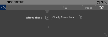
First let's simplify things further. Click on the DDLB (drop-down list box) icon  to the right of Cloudy Atmosphere and select None.
Time of Day and Time of Year
Now we have a black sky. The red line up the middle indicates the path of the Sun across the sky. Click the Time icon near the upper left corner of the RTR Window. This opens the Time Editor.
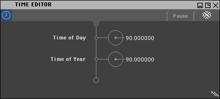
Drag the horizontal bar in the Time of Day circle  until it's somewhere around 170 to 175 degrees. You'll see a little white circle moving along the red line in the RTR Window. That's the sun! This is how you change the time of day in MojoWorld.
Next rotate the Time of Year control  and see how the red line indicating the sun's path swings back and forth across the screen. This corresponds to the seasonal change in the angle of the ecliptic. This will become more relevant in future versions of MojoWorld, when planets reside in solar systems.
Move the Time of Year control back to near 90, the Time of Day control to somewhere near 45 and then stow the Time Editor by clicking the Minimize icon  at the upper right. The Time Editor moves into the Editor Stow area
 to the lower left of the RTR Window. This handy feature lets you have lots of editors open in MojoWorld without cluttering your screen.
Texturing the Celestial Sphere
One of the cool things about MojoWorld is that you can “paint” anything onto the sky dome, or celestial sphere representing outer space. (Don't get too attached to this feature—in the future outer space in MojoWorld will become a three dimensional volumetric texture!)
Let's put some stars in the sky. We're not going to get very involved yet, we'll just be loading a starry backdrop from the library. We're starting with baby steps.
Click the Stars Editor icon  in the Global Parameters Hot Buttons to open the Stars Editor. Use the menu icon in the Stars Editor to select Load from Library.
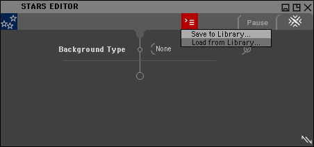
Find and select the preset SimpleStarfield.mjl. Dismiss the Stars Editor by clicking the Close icon  in the upper right hand corner of the Stars Editor window.
Let's have a look at our handiwork now. Click the Crop Window icon above the RTR Window to open a Crop Window. Drag on the Crop label  to move the Crop Window up into the sky. Also note that you can resize the Crop Window by dragging on the upper left or lower right corners.
Select Normal from the Render Quality menu.
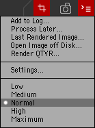
Click the Camera icon and you'll see that the sky is no longer black, but has lots of stars of varying sizes. Click the Crop Window icon  again if you'd like to dismiss the Crop Window. (You may want to leave it open for the work we're about to do.)
Creating an Atmosphere
Now let's create a planetary atmosphere for blue skies. In the Sky Editor select Cloudy Atmosphere from the Atmosphere DDLB.
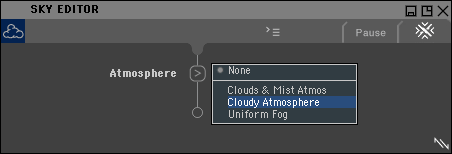
Presto! You now have blue skies. If you open the Control Stack for the Atmosphere by clicking on the Control Stack icon,  you'll find all kinds of controls. You'll also want to resize the Sky Editor window by dragging on the resize icon
 in the lower right.
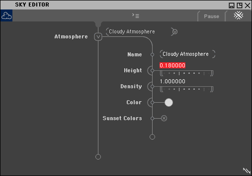
You can read about all those controls in the MojoWorld manuals. For now, just change Height to 0.18 and we'll move on. Collapse the Control Stack for Atmosphere by clicking the Close Control Stack icon. 
Creating a Cloud Layer
Let's add some clouds. Select Add New Cloud Layer from the menu in the Sky Editor.
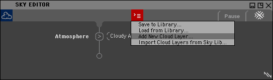
Select Cloud Layer from the Cloud Layer DDLB.
Open the Cloud Layer Control Stack. Click the semicircle icon next to Cloud Density and choose Texture from the menu.
This opens MojoWorld's ultra-powerful Texture Editor. From the menu icon at the top, select New Texture.
Click on the ghosted Circle-T icon once to enable the first texture leaf. Click it a second time to expand the new texture leaf's Kickstand.
The first thing you always want to do when creating a new texture of any kind is to name it. If you don't, after you've been working for a while you'll accumulate lots of textures and texture nodes with similar names which you can't tell apart. So highlight “Main Texture Node” and change it to “Simple Clouds 01.” (It's a good practice to append a number to your names in case you want to use the same name again for a different item, so we'll append “01” to a lot of our names throughout this tutorial.) Similarly, change the Texture Leaf Name from “Texture Leaf” to “Simple Clouds.”
Now click Monofractal to open its Control Stack and rename “MonoFractal” to “Clouds 01.”
Now for one of the ways you have to train yourself to think when using MojoWorld: By default planets in MojoWorld have a radius of 6,000,000 (six million) meters, or 6,000 kilometers (a kilometer being 1,000 meters by definition). That's approximately the same radius as planet Earth. It's really big. So one of the first things you have to do when working in MojoWorld—unlike any other 3D graphics software—is to think big. Think really big. Since MojoWorld can't know what purpose you're using anything for when you create it, its default values are usually way off. You need to adjust them immediately to the size you have in mind.
To make your clouds realistically big for a planet, change the Largest Feature to 100,000. This changes the largest cloud “blob” from one kilometer (1,000 meters) in size to 100 kilometers, or the size of a weather system on Earth.
Then there's the very powerful Roughness control. You should take a little time to familiarize yourself with its effects. Let's do a few experiments right now. Set your Render Quality to Low and make a test rendering with Roughness set at the default value of 0.375. Now change Roughness to 0.25 to make the clouds very soft; try a test rendering of that. Next try 0.75—very tattered clouds! Finally, set Roughness to 0.5 and leave it there. Roughness is one of the most potent controls in MojoWorld. Think of it as controlling the visual complexity or “busy-ness” of your textures and terrains. Be sure to experiment with it every time you create something in the Texture Editor.
Crop Window rendering of clouds with Roughness of 0.375 and 0.25.
Crop Window rendering of clouds with Roughness of 0.7 and 0.5.
This is what your Texture Editor window should look like at this point:
A rendering at Normal quality should now look like this:
Okay, now we have a nice simple sky and atmosphere. Let's make some mountains!
Creating the Land
MojoWorld terrains are simply grayscale textures, so we create them in the Texture Editor, too. The grayscale texture serves as a displacement to the spherical planetary surface. (Displacements are what MojoWorld is all about. You can even displace your displacements in MojoWorld, yielding terrains with overhangs, but that's an advanced topic.) Generally the idea is to have this displacement texture look like natural terrain—mountains. Sometimes we'll do fantastical displacements, though, “just because we can.” MojoWorld users do some really wild stuff that makes for some mighty interesting “planets.” :-)
Creating the Terrain Shape
Go back to the lower group of Global Parameters Hot Buttons. Under the Mountain icon click the Circle-T icon. This opens the Texture Editor again. Select New Texture from the menu.
Click twice on the Circle-T in the Texture Editor to open the Kickstand for our new texture. Rename “Main Texture Node” and “Texture Leaf” to “Simple Terrain 01.”
Now we want to change the type of fractal we're using. Click the DDLB icon next to MonoFractal and select Mountain Fractal.
HOT TIP: The reason you don't see anything happen to the surface of the planet immediately is that the texture's result scale is 1 meter, by default, while the RTR samples the planet surface at 2 meter intervals. Therefore the default texture results in a planet that is essentially flat. The details that are present are too small to be resolved in the RTR!
We'll fix that by scaling our texture up to where it's mountain-sized. Make the biggest mountains about 100 km (~60 miles) across by changing Largest Feature to 100,000. Make them about 10 km (~30,000 feet) high by changing Result Scale to 10,000. Now you'll see some terrain pop up in the RTR Window.
Something just happened in your RTR Window—the mountains just grew up right under the camera, and now we're right down on the surface. How can we tell? Look at the Nav Console to the lower left of the RTR Window:
The AGL field indicates how high we are above ground level. (ASL tells us how high we are above sea level, but since we don't have an ocean yet so it doesn't mean much—but it does tell us that the mountains pushed the camera up over four kilometers!)
Click in the RTR Window to move MojoWorld's input focus there, then hit the “b” key on your keyboard. This automatically pops us up to 10 km AGL with the camera level—a very handy keystroke to remember!
A rendering at Normal quality should look like this:
Next we'll make the terrain more interesting by building it out of a different Basis Function. Click on the Basis Function DDLB icon to the right of Value/Gradient Perlin and select Ridged Value.
Once again, the mountains pushed the camera up. Click in the RTR Window again and hit the “b” key to move the camera up to a decent altitude for viewing the terrain. A rendering at Normal quality should now look like this:
Okay, now we have some simple terrain. Let's add some color to it.
Adding a New Material
Click the red Circle-M icon beneath the Mountain icon in the Global Parameter Hot Buttons to the left of the RTR Window. This opens MojoWorld's Material Editor for the material applied to the planet.
Click on the Circle-M icon to the left of Displacement Material to open the material's Control Stack. Rename “Main Material Node” to “Simple Material Node 01” and rename “Displacement Material” to “Simple Material 01.”
Now we'll drive the Diffuse color channel with a texture. Click on the Semicircle icon next to Diffuse and select Texture from the menu.
Once again, this opens the Texture Editor. Select New Texture and click twice on the Circle-T icon to open the Kickstand. We're going to build a simple color-by-altitude texture for our terrain. Start by renaming “Main Texture Node” to “Color by Altitude Node 01” and renaming “Texture Leaf” to “Color by Altitude 01.”
Next click the DDLB icon next to World Position and select Altitude.
If you do a rendering at Normal quality now you'll see that we have a grayscale texture consisting of a fractal distribution of horizontal bands which resemble bedrock.
You might want to save this for later use. You can do that by selecting Save As from the File menu at the upper left of the main MojoWorld window (PC) or on the top menu bar (Mac).
Let's add some color. First turn off the fractal driving the color by selecting None from the DDLB for Monofractal.
We want this texture to be relative to Sea Level, so that when we move sea level up and down, the color at the coast remains constant. We accomplish this by clicking the circle next to Use Sea Level in the Control Stack. We get at the color Gradient by clicking Output Control on the Kickstand. Rename “Texture Color Control” to “ Color by Altitude Gradient 01” in the Name field of the Control Stack.
Open the Gradient Editor by clicking the Gradient icon in the Control Stack. Click the small black circle directly beneath the left end of the Gradient to modify the color there.
Click the Color Dot in the middle of the Gradient Editor to open the Color Picker. Drag the Color Location icon up and to the left to where we see a shade of ocher in the Color Picker.
Slide the Saturation Bar up to where you get a nice sand color and click OK.
Click the bottom edge of the Gradient near the middle to add another color node to the Gradient. Make this a dark green to represent vegetation.
Add a blue-grey node toward the top of the Gradient to represent stone, and a reddish one towards the bottom to represent scrub.
Click OK to exit the Gradient Editor.
Now we need once again to adjust things to the huge planetary scale of MojoWorld. Click on the Curve icon to the right of Input Curve. This opens the powerful Curve Editor. You can evoke any number of effects using the Curve Editor, but for now we'll just use it to adjust the scale of our coloring by altitude.
Here's what we need to do: As MojoWorld has no way of knowing the scale at which you're going to use an effect, it just defaults to reasonable values such as 0.0 or 1.0. We want to color our terrain with our color Gradient from Sea Level to the mountain tops. By default the gradient goes from 0.0 to 1.0, or from Sea Level to one meter in altitude—not what we have in mind at all. We want to apply from Sea Level to the mountain tops. Sea Level is at zero altitude, so that's okay. The mountain tops are around 20,000 meters high (the Mountain Fractal and Ridged Value Basis Function we used to create them makes them larger than the 10,000 meters we specified). We therefore want to change the input range from 0.0 to 1.0, to 0.0 to 20,000. We do this by changing Max Input value in the Curve Editor from 1.0 to 20,000.
Now you'll see color on your terrain in the RTR Window. Drag up in the RTR Window to point the camera down and rendering at Normal quality will yield a picture like this:
Things look pretty dry down there, though, so we'll fix that by adding an Ocean to our planet.
Adding an Ocean
Adding an ocean to a planet is easy. Clicking on the Water icon in the Global Parameters Hot Buttons opens the Water Editor. Select Create Ocean from the menu there.
Change the Name from “Ocean” to “Simple Ocean” and Sea Level to 1500.0. Then click on the Circle-M icon to open the Material Editor.
Select New Material from the menu in the Material Editor.
First thing, change the Material Name to “Ocean Material 01.”
Click the Circle-M icon to the left of Displacement Material to open the material's Kickstand. Click the DDLB icon to the left of Displacement Material in the Kickstand and select Water Material.
This opens the Control Stack for the Water Material. Change the Name from “Water Material” to “Simple Water 01.”
You can see that there are a lot of controls available for water materials. The one that's most fun to play with is the Murkiness value. Change it to 0.0 for extremely clear water. Try values of 10, 100 and 1,000 and see how the water gets murkier to the point where it's downright muddy. MojoWorld uses an accurate simulation of light propagation through water to get these effects. Let's leave Murkiness at the super-clear water value of 0.0 and move on.
To see what our water looks like, click the Water icon in the Global Parameter Hot Buttons area again to open the Water Editor. Set Sea Level to 3,000 and the water will rise up in the RTR Window. A rendering at Normal quality will look like this:
To finish this tutorial, let's add some waves to the Water material.
In the Material Editor for the Ocean, click the Semicircle icon for Displacement and select Texture. This opens the Texture Editor once again.
Select New Texture from the menu. Click twice on the Circle-T to open the Kickstand for our new texture. Rename “Main Texture Node” and “Texture Leaf.“ Click on MonoFractal to open its Control Stack. From the Basis Function DDLB select Voronoi to give us waves with sharp crests and rounded troughs.
Click on the Zoom In icon beneath the top Texture Preview Window to get a closer look at the texture.
We don't want our water to be too rough, so reduce Roughness to 0.2. Next we want to scale the waves to be realistic in size and character. Let's make our largest waves 100 meters (~300 feet) in horizontal size by changing Largest Feature to 100. You may need to zoom in some more to see the texture well. We want to make our waves about 15 feet high, so set Result Scale to 5.0 meters.
Walking the camera down to within 30 meters of the ground next to the shoreline and taking another render at Normal quality looks like this:
You may notice that MojoWorld is rendering more slowly now than it was in the beginning. That's because is has much more work to do now, evaluating all the textures we've created. Getting down close to the surface also slows things down, as there are more levels of detail required to image everything at pixel-level detail. It's not easy to pull this off; MojoWorld has a lot of work to do to image even this very simple world we've created.
Epilog
We've built a new planet entirely from scratch. We didn't get into exploring it, but it's there, waiting. It's a very simple planet and not all that interesting as MojoWorlds go, as this shot from deep space illustrates:
Down a lot closer to the surface, though, it's more interesting:
Simple as this planet is, I think it's pretty darn cool that it was built with relatively little effort—for a whole Earth-sized planet!
As much work as we did, we barely scratched the surface of MojoWorld's capabilities, most of which have yet to be explored and exploited by anyone at the time of this writing, three years after the introduction of MojoWorld Generator 1.0.
I've been working towards MojoWorld rather single-mindedly since 1987. In all that time of plotting and planning, I never anticipated just how much work it would take to create a really interesting planet the size of Earth. It's such a big job that, even only six months after the introduction of MojoWorld Generator, I can hardly imagine starting a new planet entirely from scratch. I'd always start with an existing planet that I like and make modifications to it. (MojoWorld Generator has a Planet Info feature in the File menu that lets us track authorship and changes to MojoWorld files. I expect that a few years from now, the really interesting planets will have a list of people who've contributed to their beauty.)
At any rate, expect it to take some time to build interesting, original planets of your own. Heck, it always took me many days of work to generate just one nice still image of a relatively small “stage set,” in my years of creating proto-MojoWorld artworks. MojoWorlds are far more than beautiful, static images—they are full planets that may be home to countless beautiful images, all just waiting to be discovered. MojoWorld is the first 3D graphics application that deals with more than strictly local “stage sets.” Only MojoWorld takes the global view. MojoWorlds are huge places and should be varied. Introducing these variations will take lots of work, no doubt about it. But the results can be positively mind-bending. (See Armands Auseklis' MojoWorld Galleries for some of my favorites.)
You're probably using the free MojoWorld Generator Demo when you're reading this. If you get hooked and feel the need to be the creator of your own entirely new planets, please buy MojoWorld Generator and support Pandromeda's ongoing efforts to refine and improve the tools that open up the Mojoverse to all Earthlings.
Welcome aboard, Mojonaut! We hope you enjoy the adventure. And don't forget to share with the rest of us the beauty you discover in your images, animations and QTVR panoramas. Remember that MojoWorld files are generally amazingly compact, so pick them up freely over the Internet and share in the adventure of exploring this parallel universe we call the Mojoverse.
-Doc Mojo Musgrave, Oct 14, 2004
MojoWorld Feature Tour (Archived from Pandromeda)
All text and images remain property of Pandromeda Inc, they have only been reproduced here for historical, non-commercial, and preservation purposes. Archived source obtained from: http://www.pandromeda.com/products/mojoworldprofeatures.php | mojoworldstandardfeatures | mojoworldfocusfeatures
Index: New 3.1 Features, World Creation and Editing, Local Terrain Import and Editing, Object Creation, Import and Editing, Navigation and Camera Controls, Rendering Tools, Users Manual and Interactive Help,
New 3.1 Features
Native .pz3 Poser Import: Importing of Poser figures directly from their native .pz3 format now creates many more custom textures and materials to get your Poser figures into your MojoWorlds with no extra texture tweaking required!
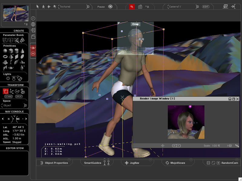
Poser 6 Strand-based Hair Support: A new material type provides full support for Poser 6 Strand-based Hair. This material is created automatically upon import of the Poser figure.
Quick 'Draw As Box' Toggle for Poser Figures: Poser figures come into MojoWorld drawn in the RTR in the Poser 'Draw As Box' mode. This is less demanding on the video card. A small widget near the figure's bounding box allows the preview to be quickly toggled to a detailed view without opening the figure's editor.
Improved Preview Handling for all Imported Models: The detail shown in the Real-Time Renderer OpenGL preview for all models can be specified. When creating a forest of a single plant model, the detail is shared between the models, so changing it for one changes all. This allows fast RTR response and low memory usage.
lodmanagement_SM.jpg + lodmanagement_B.jpg were never captured
MorphGrid Terrain Shaping Tool: The new MorphGrid primitive lays a network of point handles onto the surface of the planet. These points can then be pushed or pulled to re-shape the terrain interactively.
morphgrid_SM.jpg + morphgrid_B.jpg were never captured
Rendering Enhancements: Improvements in shadow rendering and in rendering objects submerged in refractive water contribute to the photo-realism of MojoWorld renders.
renderingenhance_SM.jpg + renderingenhance_B.jpg were never captured
Improved MultiMaterial Preview: Previously, the preview swatch for a multi-material would show only the characteristics of the first material leaf. With the 3.1 update, the preview swatch area divides itself up into sections, with a section previewing the charcteristics of each material leaf on the Nested Material Tree.
World Creation and Editing
Full Planet Creation with Astronomical Context: Landscapes have a global context: the surface of a planet. Planets have a context: the cosmos. MojoWorld lets you create them all: terrain, oceans, atmosphere, clouds, suns, moons, planetary rings, and starry skies.
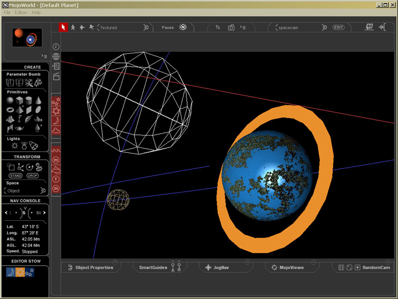
Complete Editor Set with Detailed Controls: MojoWorld's complete set of editors lets you control minutiae of everything on your world and in the sky beyond. You can set the MojoWorld UI to a variety of complexity levels that scale between simplicity and complete control.
Procedural Fractal Textures: The magic of MojoWorld is based on fractals. MojoWorld features the world's most advanced and versatile random fractal engine for creating an unlimited variety of fractal natural phenomena.
MojoGraph™ Pro UI: A user interface usually limits what you can do. But not in MojoWorld—the MojoGraph Pro UI lets you build custom shaders interactively. There is literally no limit to the power or complexity of what you can build in MojoGraph. Available only in MojoWorld 3 Professional!
mojograph_SM.jpg + mojograph_B.jpg were never captured
Planet Wizard 3 Instant Worlds: Want instant gratification? MojoWorld 3's all-new Planet Wizard 3 will create entire planets for you—billions and billions—with a single click! You can explore them click-by-click with the RandomCam, too. It's both endless fun and a great productivity tool.
planetwizard_SM.jpg + planetwizard_B.jpg were never captured
Huge Content and Vegetation Library: Terrains, materials, oceans, vegetation, atmospheres, starry backdrops, planetary rings; you name it! MojoWorld ships with an assortment of over 50 high quality plant models from 3DPlants.com.
hugecontent_SM.jpg + hugecontent_B.jpg were never captured
MojoTree™ for Procedural Forests: Quickly and easily populate any region in your MojoWorld with procedural forests using MojoTree. Use trees from the preset libraries or custom objects you build yourself in the powerful MojoTree editors. Includes over 30 procedural tree species! MojoWorld 3 Professional includes MojoTree; MojoTree can also be purchased separately to extend the power of MojoWorld 3 Standard
mojotree_SM.jpg + mojotree_B.jpg were never captured
MojoMove™ for Procedural Animation: MojoMove animates your clouds, stars, water, terrains, and even your sun and moons. MojoMove includes an extensive library of animated content ready to use on your own planets. Build your own MojoMove content with MojoGraph in MojoWorld 3 Professional. MojoWorld 3 Professional includes MojoMove; MojoMove can also be purchased separately to extend the power of MojoWorld 3 Standard.
mojowove_animate.gif was never captured
Local Terrain Import and Editing
Import from Other Terrain Apps: You can import terrains from other apps and add detail to them in MojoWorld, smoothly blending them into your planet. No need to leave your Corel Bryce 5 terrains behind!
terrainimport_SM.jpg + terrainimport_B.jpg were never captured
Export to Other Terrain Apps: You can export MojoWorld 3 terrains—even entire planets—with or without textures, for use in other apps.
terrainexport_SM.jpg + terrainexport_B.jpg were never captured
Parameter Bombs™ for Local Control: "Think globally, act locally"—build familiar local terrains using MojoWorld's powerful Parameter Bombs. A Parameter Bomb is a local area on a MojoWorld planet—of any size you determine—where everything can be different than on the rest of the planet, and with a seamless blend between the two. Put an oasis on a desert planet—it's easy with a Parameter Bomb!
parameterbomb_SM.jpg + parameterbomb_B.jpg were never captured
Fractal River Networks: A MojoWorld exclusive: complete continents with fractal river networks! It took our resident astrophysicist to figure out how to do this. The results are a level of realism and environmental fidelity that's only possible in MojoWorld.
riverterrain_SM.jpg + riverterrain_B.jpg were never captured
Layout Mode Easy Scene Composition: Create your digital masterpiece in Layout Mode, where all of your 3D objects and MojoFX special effects are right at your fingertips. Layout Mode combines the ease of use of a traditional 2D program like Adobe Photoshop with 3D photorealistic MojoWorlds.
riverterrain_SM.jpg + riverterrain_B.jpg were never captured
Object Creation, Import and Editing
Interactive Object Manipulation: Create, transform, and place objects accurately, on-screen, using the powerful new positioning and editing tools—with unlimited undo/redo. Click on any object to instantly learn its name, size, position, rotation, and location on your planet, with dynamic feedback as you make changes. Spin your camera around a given object.
interactiveobjectman_SM.jpg + interactiveobjectman_B.jpg were never captured
Easy Object Transformations: Drop objects to the ground or stand them straight up. Interactively specify the point about which a given object is rotated for precise control.
easyobjtransform_SM.jpg + easyobjtransform_B.jpg were never captured
SmartStamp Cloning: MojoWorlds were meant to be filled with objects—lots of objects! For this, we have the SmartStamp: it will duplicate your objects at either a fixed distance from the camera or fixed height above the ground. In MojoWorld 3 Professional, you can also have them duplicated with a random rotation and/or a random scaling factor—very useful for creating realistic vegetation from a small number of models.
smartstampcloning_SM.jpg + smartstampcloning_B.jpg were never captured
Smart Guides Precision Tools: With new SmartGuides, laying out a 3D scene is as easy as it is in any 2D application. Visually align and place objects with the Ground Lines Guide and Object Alignment Guide, and always know where objects are in relation to the terrain and each other.
smartguides_SM.jpg + smartguides_B.jpg were never captured
2D PhotoBillboard Integration: Place your favorite 2D photos or artwork in your MojoWorld with a click! They are inserted as a 3D object, support transparency, and can be made to remain facing the camera as it moves around.
photobillboards_SM.jpg + photobillboards_B.jpg were never captured
Spotlights with Gel Effects: You can automatically point MojoWorld's new interactive spotlights at any object in your scene. Spotlights can remain locked onto the object for interactive rotation around the target, producing striking, object-based lighting. Add gels to your spotlights for dramatic stagelighting effects.
fxspotlight_SM.jpg + fxspotlight_B.jpg were never captured
Industry Standard Model Imports: MojoWorld reads and writes to the industry standard file formats for seamless integration with your other 3D modeling and rendering tools. Built-in support for DXF, OBJ, LWO1 and 3DS formats.
industryimport_SM.jpg + industryimport_B.jpg were never captured
New Boulder Tool: MojoWorld's Boulder Tool lets you place as many unique stones as you like all over your worlds. You get the Boulder Tool when you register your copy of MojoWorld with Pandromeda.
bouldertool_SM.jpg + bouldertool_B.jpg were never captured
Interactive Real-Time Exploration: MojoWorld's real-time front end lets you move around your worlds interactively. You can even lay down an animation path as you go! Tools that are overlaid on the real time front end pop up then fade away when not being used, to simultaneously maximize convenience of use and your screen real estate, and minimize their interference with your exploration.
navigationandcamera_SM.jpg + navigationandcamera_B.jpg were never captured
Intuitive Navigation Modes: MojoWorlds are vast, and you need to be highly mobile to explore them. Use the GPS Globe to place yourself directly at any spot you like, anywhere on your planet. Walk, Fly, and UFO modes let you move about freely—and record animation along the way. MojoWorld's exclusive UFO mode lets you do zooms from space down to the surface of the planet quickly and easily, without crashing into the planet because you're going too fast.
intuitivenagivation_SM.jpg + intuitivenagivation_B.jpg were never captured
JogNav Trackball Navigation: A pop-up trackball camera control to provide quick and easy navigation through your worlds—and dynamic adjustment of the camera's field of view, too. Keep it on screen all the time or hide it from view, at your option.
jognav_SM.jpg + jognav_B.jpg were never captured
RandomCam Instant Exploration: MojoWorlds are huge and you never know what you'll find or where you'll find it. Explore quickly by teleporting to a random location on the daylight side of the planet, or a random view within your locale. Instantly return to locations with a single click.
randomcam_SM.jpg + randomcam_B.jpg were never captured
MojoViews Positioning Cameras: With MojoViews, you can look at an object or point on the terrain from various points of view, while preserving your main camera point of view, with MojoViews. Zoom in and out, too, for precise object placement. In MojoWorld 3 Standard, you can switch between the Camera View and Top View. MojoWorld 3 Professional supports multiple views: Camera, Top, Bottom, Front, Back, Left, and Right.
mojoviews_SM.jpg + mojoviews_B.jpg were never captured
Intuitive Library Management: MojoWorld library items feature thumbnail previews so you can see clearly what you're getting. Iterative loading lets libraries load fast, with improved navigation methods. With MojoMove, library previews are even animated!
librarymanagement_SM.jpg + librarymanagement_B.jpg were never captured
Rendering Tools
Real Time Renderer: For interactive exploration of the vast worlds that MojoWorld creates, and for quick visualization of changes to worlds you're building, MojoWorld's Real Time Renderer gives you the freedom and feedback you need. Now you can see your clouds in MojoWorld's Real Time Renderer—even when they're animated!
realtimerenderer_SM.jpg + realtimerenderer_B.jpg were never captured
Zip Render Instant Preview: Not everything in a MojoWorld can be rendered in the Real Time Renderer. For fast previews, there's the Zip Render window. Amazingly quick, it can provide a thumbnail rendering of what your final scene will look like.
ziprender_SM.jpg + ziprender_B.jpg were never captured
Photorealistic Hybrid Renderer: MojoWorld's breakthrough Photorealistic Render provides pixel-level detail in both geometry and textures, overhangs in the terrain (another MojoWorld exclusive), soft shadows, and realistic reflection and refraction. This hybrid renderer uses micropolygon scanline rendering for speed and ray tracing for realism.
hybridrenderer_SM.jpg + hybridrenderer_B.jpg were never captured
Uplink Queue Batch Rendering: MojoWorld's Uplink Queue lets you store as many rendering jobs as you like to render later, while you sleep, go on vacation, or whatever. It's a great productivity tool!
uplinkqueue_SM.jpg + uplinkqueue_B.jpg were never captured
Huge Rendering Resolution: MojoWorld features pixel-level detail at any resolution, field of view, or distance, so there is no theoretical limit to how big you can make your final images. MojoWorld Professional's resolution is limited only by your hardware. MojoWorld Standard supports up to 7,500 pixels on a side for stills and 1024 for QTVR panoramas.
hugerenderingresolution_SM.jpg + hugerenderingresolution_B.jpg were never captured
360 Degree Cubic QuickTime VRs: Anywhere you go, you can render a QTVR panorama that gives you a real sense of being there. You can look straight up, straight down, and all around. MojoWorld's unique pixel-level detail gives you unmatched realism, and QTVRs show it off stunningly. With MojoWorld 3 Professional, you can enhance your QTVR panoramas with Hot Spots: areas of the panorama that serve as links to URLs, other QTVRs, text documents; you name it!
qtvrexport_SM.jpg + qtvrexport_B.jpg were never captured
Zoom to Crop Window and Render: Zoom your camera to the view contained in the Crop Window. Preview in the Zip Render Window or just render whatever you've zoomed! The Crop Tool lets you interactively select any part of your image and render only it.
cropzoom_SM.jpg + qcropzoom_B.jpg were never captured
Industry Standard Render Resolution Settings: New presets let you render to industry-standard resolutions and aspect ratios—such as HDTV, video, etc.—quickly and easily.
industrystdrenderres_SM.jpg + industrystdrenderres_B.jpg were never captured
Users Manual and Interactive Help
User Manual & Quick Start Tutorials: In MojoWorld 3, the industry's best user manual gets even better with expanded reference sections for both beginners and advanced users.
manual_SM.jpg + manual_B.jpg were never captured
Interactive On-Line Help: The new and improved MojoWorld Help System provides complete documentation to the entire application. New search features and chapter-by-chapter layout provide easy access to everything you might want to know about MojoWorld.
Integrated Community Access: Launch MojoVox™, Pandromeda's private chat utility for Mojonauts, or visit mojoworld.org, the MojoWorld community web site! Get instant and direct access to all manner of information on MojoWorld, and the expertise of fellow MojoWorld users.
Bejeweled 2 MojoWorld Backgrounds
You can view them from a variety of sources, but be advised they still remain property of Armands Auseklis (PopCap/EA simply licensed them). It's possible they commissioned future ones for Bejeweled Twist instead of public licenses from Zazzle, but I really do not know.
- Bejeweled 2 Fandom Wiki
- Armands' Official Deviant Art
- Armands' TerraEscape site from Wayback
- Backgrounds posted in a Reddit thread
Fun fact: Armands used Dmytry Lavrov's volumetric plugin for some of them, that's how the really chunky clouds were achieved.